3
20142714
Installation
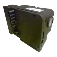
The MG569-BWZG control box is installed on one-stage and two-
stage burners.
Burner equipment
Control box . . . . . . . . . . . . . . . . . . . . . . . . . . . . . . . . . . . . . No. 1
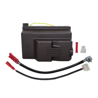
Safety lockout device V2 . . . . . . . . . . . . . . . . . . . . . . . . . . No. 1
RS safety lockout device and connection. . . . . . . . . . . . . . No. 1
SO Connection . . . . . . . . . . . . . . . . . . . . . . . . . . . . . . . . . . No. 1
Connection assembly . . . . . . . . . . . . . . . . . . . . . . . . . . . . . No. 1
Instruction. . . . . . . . . . . . . . . . . . . . . . . . . . . . . . . . . . . . . . No. 1
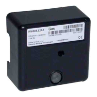
To install the new MG569 - BWZG control box, it is necessary to
use the diagram below.
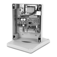
Key to layout (Fig. 2)
PG - Gas pressure switch
PA - Min. air pressure switch
MV -Fan motor
V1 - Gas valve 1
st
stage
V2 - Gas valve 2
nd
stage
SM - Servomotor (for prepared burners)
SO - Ionisation probe
RS - Remote reset
2 Installation
MG569
568 - 569
566SE Rev.3
MG569 - MWZG
MG569 - BWZG
MG569 - BWZG
525SE/G - 566SE
566SE Rev. 1 and Rev. 2
MG569 - BWZG + Assem-
bly connections
All the installation, maintenance and dismantling
operations should be performed voltage free.
The replacement of the control box must be per-
formed by qualified personnel, as indicated in this
manual and in accordance with standards and
regulations in force.
The connection assembly (Fig. 5) must only be
used if it is necessary to replace a control box
model 525 SE/G - 566 SE - 566 SE Rev. 1 and
Rev. 2.
The control box replaces the parts code 3002949
and code 3002967.
Connecting the remote reset
Make the connection with the RS lead supplied
with the burner.
Connect a button at a max. distance of 20 metres.
E9263
SO PA SMMVV2 V1RS PG
 Loading...