2587
1
INDEX
1. BURNER DESCRIPTION
1.1 BURNER EQUIPMENT
Flange and gasket . . . . . . . . . . . . No. 1 Screw of by-pass pump . . . . . . . . . . . . . . . . . . . . No. 1
Screw and nuts for flange . . . . . . No. 1 Bolts for flange to be fixed to boiler . . . . . . . . . . . No. 4
Hexagonal key . . . . . . . . . . . . . . . No. 1 Screws and terminal screw for feeding cable . . . . No. 3
Flexible oil pipe with nipple . . . . . No. 1
1. BURNER DESCRIPTION. . . . . . . . . . . . 1
1.1 Burner equipment . . . . . . . . . . . . . . . . . 1
2. TECHNICAL DATA . . . . . . . . . . . . . . . . 2
2.1 Technical data . . . . . . . . . . . . . . . . . . . . 2
2.2 Overall dimensions. . . . . . . . . . . . . . . . . 2
2.3 Working field . . . . . . . . . . . . . . . . . . . . . 2
3. INSTALLATION . . . . . . . . . . . . . . . . . . . 3
3.1 Boiler fixing . . . . . . . . . . . . . . . . . . . . . . 3
3.2 Mounting the burner. . . . . . . . . . . . . . . . 3
3.3 Hydraulic systems . . . . . . . . . . . . . . . . . . 4
3.4 Electrical wiring . . . . . . . . . . . . . . . . . . . . 5
4. WORKING . . . . . . . . . . . . . . . . . . . . . . . 6
4.1 Combustion adjustment. . . . . . . . . . . . . . 6
4.2 Nozzles recommended . . . . . . . . . . . . . . . . 6
4.3 Electrodes setting . . . . . . . . . . . . . . . . . 7
4.4 Combustion head setting . . . . . . . . . . . . . 8
4.5 Air damper adjustment . . . . . . . . . . . . . . 8
4.6 Pump pressure . . . . . . . . . . . . . . . . . . . . 8
4.7 Burner start-up cycle. . . . . . . . . . . . . . . . 8
5. FAULTS / SOLUTIONS . . . . . . . . . . . . . . 9
■
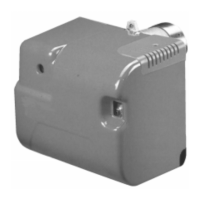
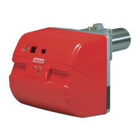
One stage kerosene and gas oil burner.
■
In case of BF applications the intake air temperature must not be over 70°C.
■
The burner meets protection level of IP 40, EN 60529.
■
Burner with CE marking in conformity with EEC directives: EMC 89/336/EEC, Low Voltage 73/23/EEC,
Machines 98/37/EEC and Efficiency 92/42/EEC.
■
CE Reg. N: 0036 0275/99 (489 T50) - 0036 0274/99 (488 T50), as 92/42/EEC.
1 – Pump
2 – Control-box
3 – Reset button with lock-out lamp
4 – Flange with insulating gasket
5 – Air damper adjustment screw
6 – Photoresistance
7 – Pump pressure adjustment screw
8 – Pressure gauge port
1
D4069
Fig. 1
4
5
2
3
7
8
6