20166443
26
Start-up, calibration and operation of the burner
2 - Min output
Max output of the burner must be set within the firing rate range
shown on page 9.
Press button 2)(Fig. 27 on page 24) “output reduction“ and keep
it pressed until the servomotor has reached 20° (factory setting).
Adjusting the nozzle flow rate
The nozzle flow rate is given in diagram (Fig. 28 on page 24) cor-
responding to the pressure on the nozzle return read on the pres-
sure gauge 1)(Fig. 29 on page 25).
The output and the pressure of the nozzle are at minimum when
the servomotor is positioned on 20°.
To set return pressure, see page 9.
Adjusting air delivery
Progressively adjust the starting profile of cam 2)(Fig. 30) by turn-
ing the screws 3).
It is preferable not to turn the first screw since this is used to set
the air gate valve to its fully closed position.
3 - Intermediate output air/oil flow rate adjustment
Press the switch 2)(Fig. 27 on page 24) “output increase” a little
so that the servomotor turns by about 15°. Adjust the screws until
optimal combustion is obtained. Proceed in the same way with
the other screws.
Take care that the cam profile variation is progressive.
Switch the burner off with switch 1)(Fig. 27 on page 24), at the
OFF position, disengage the cam 2)(Fig. 30) from the servomo-
tor, by pressing the button 3)(Fig. 31) and moving it to the right,
and check more than once that the movement is soft and smooth,
and does not grip, by rotating the cam 2) forward and backward
by hand.
Engage cam 2) to the servomotor again by moving button
2)(Fig. 31) to the left.
As far is possible, try not to move those screws at the ends of the
cam that were previously adjusted for the opening of the air gate
to MAX and MIN output.
Once you have finished adjusting outputs MAX - MIN - INTER-
MEDIATE, check ignition once again: noise emission at this
stage must be identical to the following stage of operation. If you
notice any sign of pulsations, reduce the ignition stage delivery.
Finally fix the adjustment by turning screws 4)(Fig. 30).
The servomotor follows the adjustment of cam III only when
the cam angle is reduced. If it is necessary to increase the
cam angle, first increase the servomotor angle with the key
“output increase”, then increase the III cam angle, and finally
bring the servomotor back to the MIN output position with
the key “output decrease”.
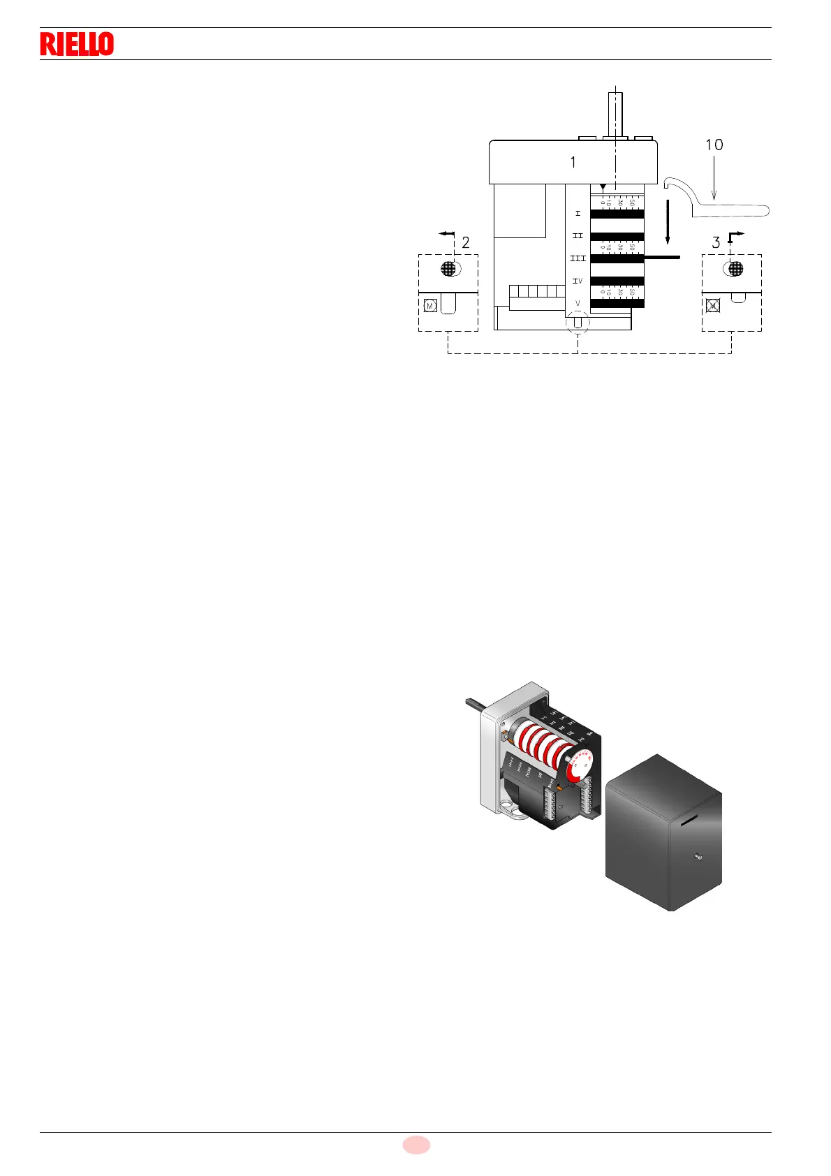
In order to adjust cam III, especially for fine movements, key
10)(Fig. 31), held by a magnet under the servomotor, can be
used.
7.3.3 Servomotor
The servomotor provides simultaneous adjustment of the air gate
valve, by means of the variable profile cam and the pressure reg-
ulator. The servomotor rotates through 130° in 42 seconds.
Do not alter the factory setting for the 5 cams; simply check that
they are set as indicated below:
Cam I: 130° Limits rotation toward maximum posi-
tion.
Cam II: 0° Limits rotation toward the minimum po-
sition. When the burner is shut down the
air gate valve must be closed: 0°.
Cam III: 20° Adjusts the ignition position and the
MIN output.
Cams IV - V: not utilized.