Installation
20008423
21
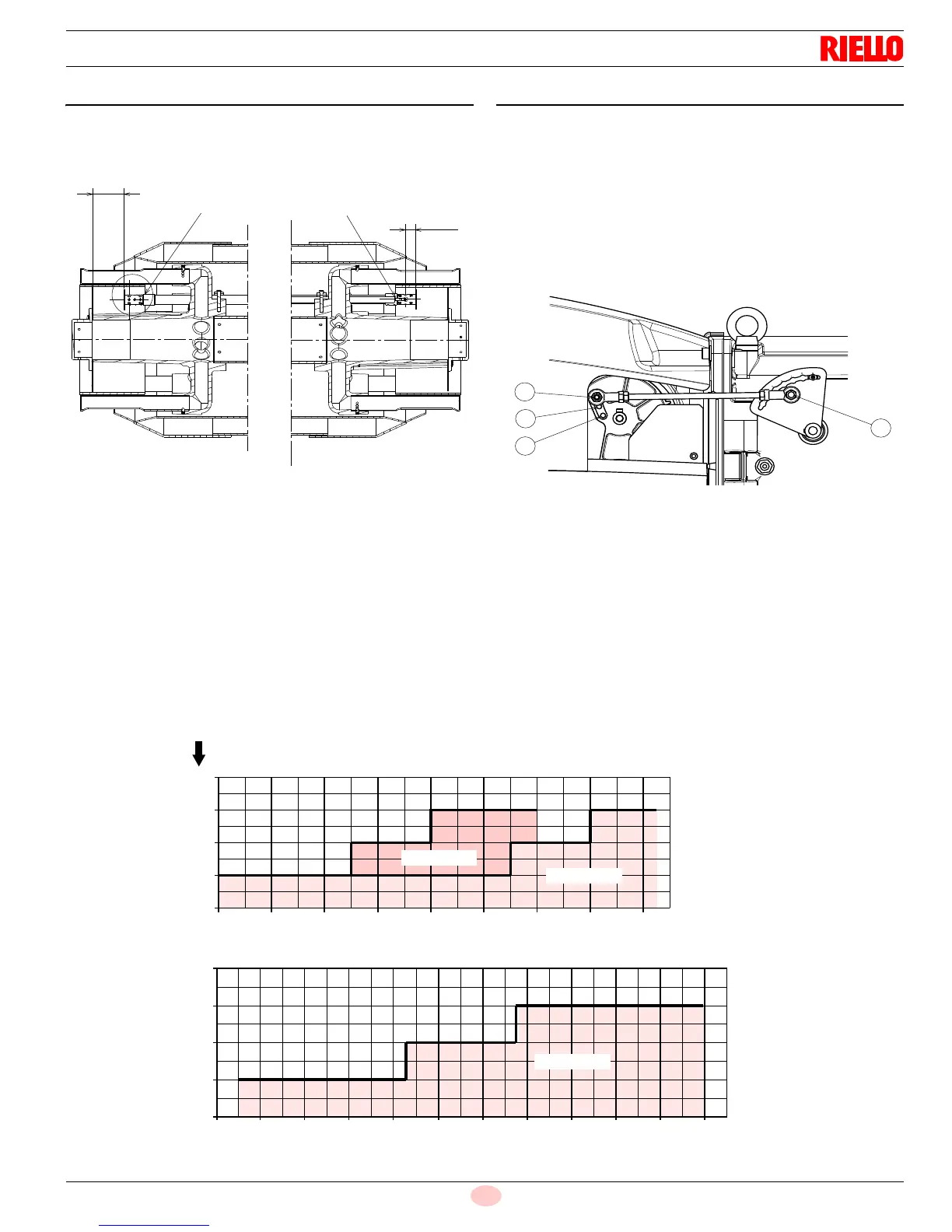
4.7 Electrode positioning
Make sure that the electrode and the ignition pilot are positioned
as shown in figure (Fig. 15).
4.8 Combustion head setting
In addition to varying air flow depending on the output request-
ed, the air gate valve servomotor 4) (Fig. 5) by means of a lifting
assembly - varies the setting of the combustion head.
This system allows an optimal setting even at a minimum firing
rate.
For the same servomotor rotation, combustion head opening
can be varied by moving the tie rod onto holes 1-2-3, Fig. 16.
The choice of the hole (1-2-3) to be used is decided on the basis
of diagram (Fig. 17) against the required maximum output.
Setting is pre-arranged in the plant for the maximum run (hole 3)
(Fig. 16).
When dealing with boilers featuring a strong back pressure, if air
delivery is insufficient even with the damper fully open, you can
use a different setting to that illustrated in diagram (Fig. 17) do
this by moving the tie rod onto the next highest hole numerically
speaking, thus increasing the combustion head’s opening and
hence air delivery.
4
2
1
0
4545 6060 7575 9090 10605 12120 13635 15150 16664
3
2
1
0
9090 10605 12120 13634 15149 166644545 6060 7575
3030
3
4
MB t u / h r
18179 19694
MB t u / h r
Fig. 17
D9402
Max burner output
RS 400/E LN
RS 500/E LN
RS 300/E LN
N° Hole