20144599
20
Installation
5.9.2 Gas train
Type-approved in accordance with EN 676 and supplied
separately from the burner.
To select the correct gas train model, refer to the manual "Burner-
gas train combination" supplied with the unit.
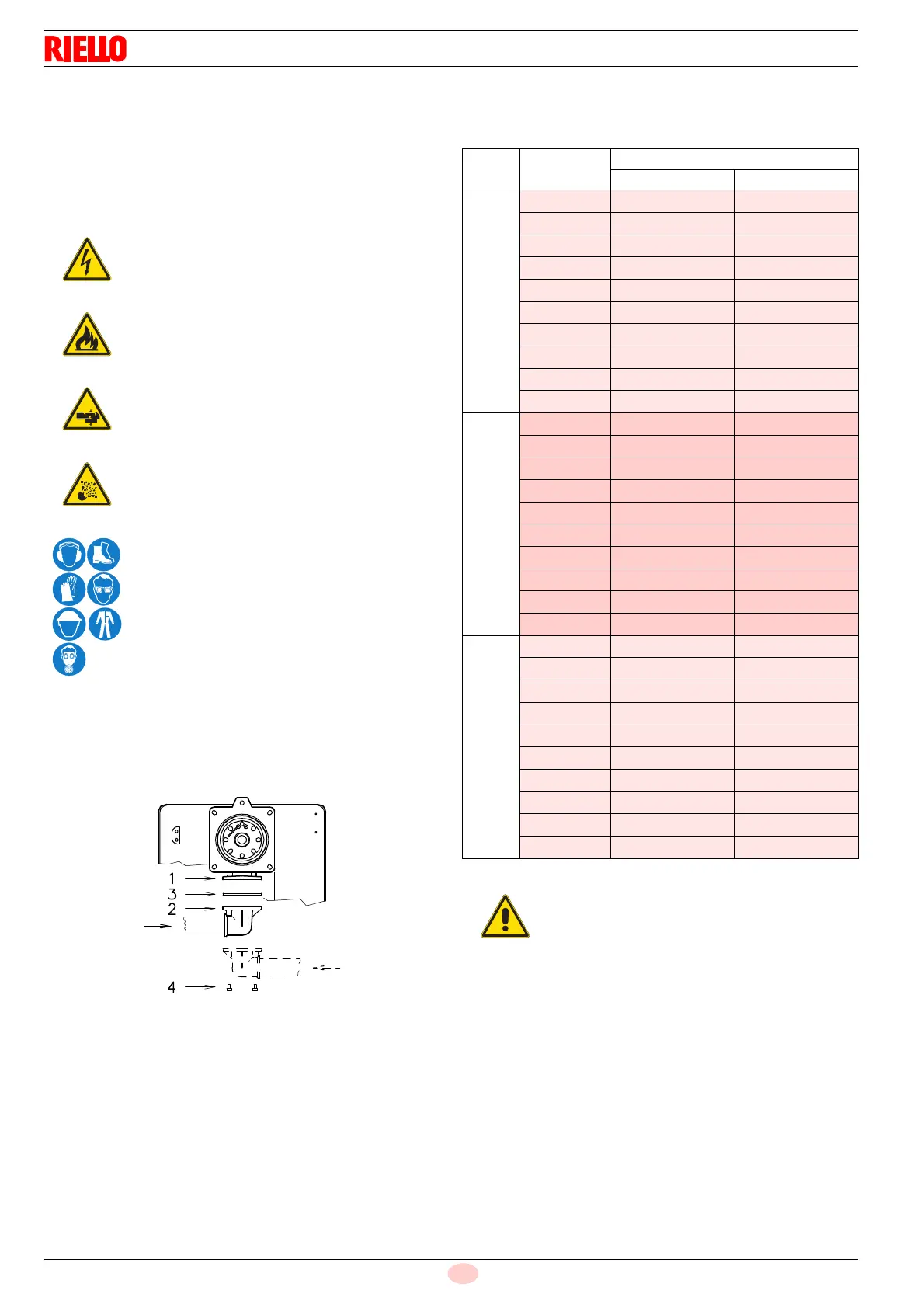
5.9.3 Gas train installation
The gas train must be connected to the gas connection 1)
(Fig. 19), using the flange 2), the gasket 3) and the screws 4)
supplied with the burner.
The train can enter the burner from the right or left side,
depending on which is the most convenient, see Fig. 19.
5.9.4 Gas pressure
Tab. F indicates the pressure drops of the combustion head and
gas butterfly valve, on the basis of the burner operating output.
Tab. F
The values shown in Tab. F refer to:
– Natural gas G 20 NCV 10 kWh/Sm
3
(8.6 Mcal/Sm
3
)
– Natural gas G 25 NCV 8.6 kWh/Sm
3
(7.4 Mcal/Sm
3
)
Disconnect the electrical power using the main
switch.
Check that there are no gas leaks.
Pay attention when handling the train: danger of
crushing of limbs.
Make sure that the gas train is properly installed
by checking for any fuel leaks.
The operator must use the required equipment
during installation.
Model kW
1 p (mbar)
G20 G25
RS 28
165 2.6 3.6
183 3.2 4.5
201 3.8 5.3
218 4.3 6
236 4.9 6.9
254 5.5 7.7
272 6.1 8.5
289 6.6 9.2
307 7.2 10.1
325 7.8 10.9
RS 38
230 2.8 3.9
253 3.2 4.5
277 3.7 5.2
300 4.2 5.9
323 4.6 6.4
347 5.1 7.1
370 5.6 7.8
393 6.1 8.5
417 6.7 9.4
440 7.2 10.1
RS 50
290 2.5 3.5
322 3.1 4.3
354 3.8 5.3
387 4.4 6.2
419 5.1 7.1
451 5.7 8
483 6.4 9
516 7.1 9.9
548 7.7 10.8
580 8.4 11.8
Data of head thermal power and gas
pressure refer to operation with gas
butterfly valve fully open (90°).
 Loading...