20144599
30
Start-up, calibration and operation of the burner
6.9 Burner start-up cycle diagnostics
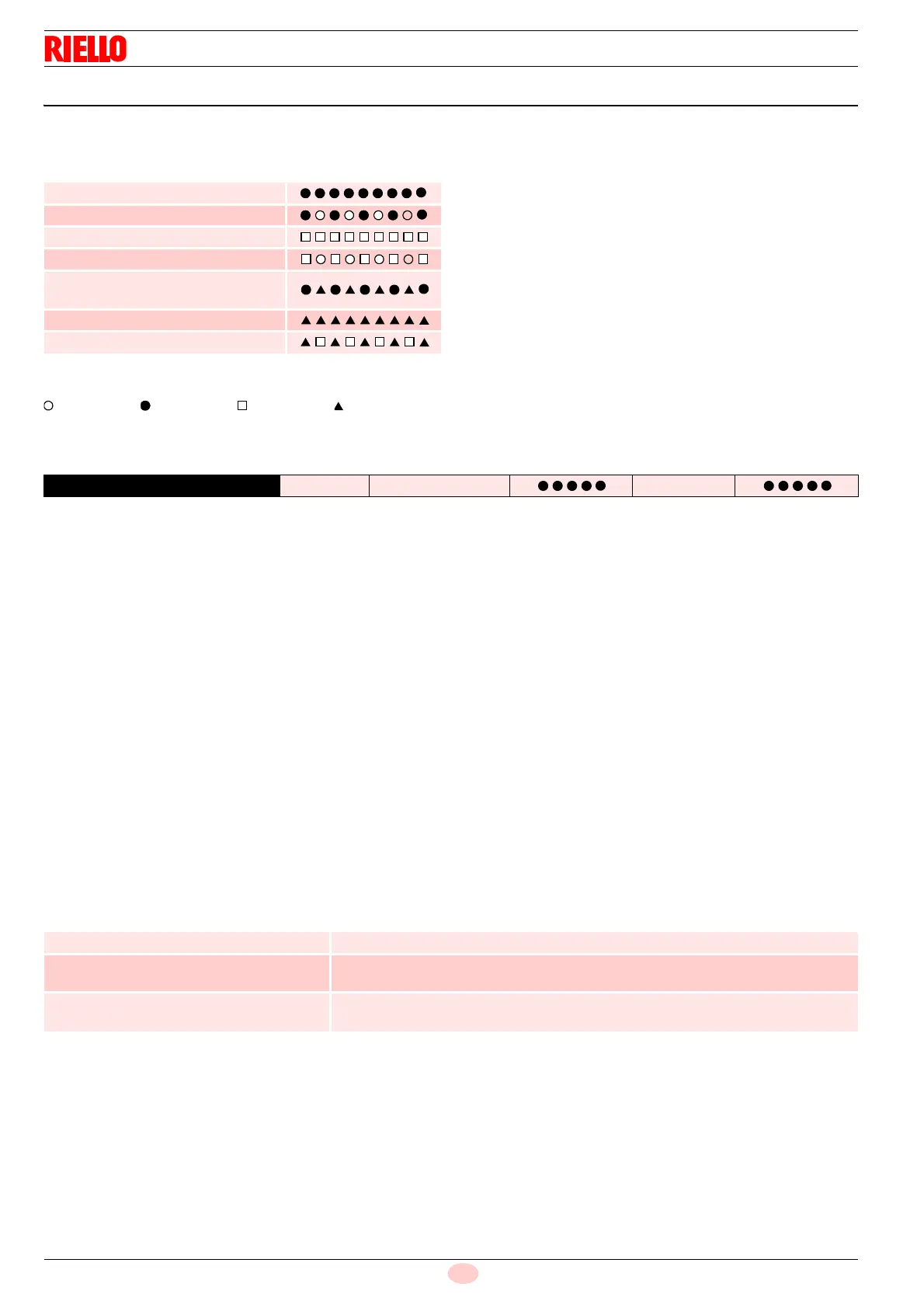
During start-up, indication is according to the colour code table
(Tab. G).
Tab. G
Key (Tab. G):
Off Yellow Green Red
6.9.1 Resetting of control box and diagnostics use
The control box supplied features a diagnostics function, through
which any causes of malfunctioning can be easily identified
(indicator: RED LED).
To use this function, you must wait at least 10 seconds once it
has entered the safety condition (lockout), and then press the
reset button.
The control box generates a sequence of pulses (1 second
apart), which is repeated at constant 3-second intervals.
Once you have seen how many times the light blinks and
identified the possible cause, the system must be reset by
holding the button down for 1 - 3 seconds.
Tab. H
Below is a list of the possible methodologies for carrying out the
resetting of the control box and for using the diagnostics.
6.9.2 Control box reset
To reset the control box, proceed as follows:
– Hold the button down for between 1 and 3 seconds.
The burner starts up again, 2 seconds after the button is
released.
If the burner does not restart, make sure the limit thermostat
is closed.
6.9.3 Visual diagnostics
Indicates the type of burner malfunction causing lockout. To view
diagnostics, proceed as follows:
– Press and hold the button for more than 3 seconds from the
steady red LED condition (burner lockout).
A yellow light blinks to tell you the operation is done.
– Release the button once the light has blinked. The number of
blinks indicates the reason for the malfunctioning (refer to the
coding in Tab. L on page 35).
6.9.4 Software diagnostics
Provides an analysis of the life of the burner, through optical
connection with a PC showing the working hours, number and
types of lockout, control box serial number etc.
To view diagnostics, proceed as follows:
– Press and hold the button for more than 3 seconds from the
steady red LED condition (burner lockout).
A yellow light blinks to tell you the operation is done.
– Release the button for 1 second and then press again for
over 3 seconds until the yellow light blinks again.
– Once the button is released, the red LED will flash
intermittently with a higher frequency: it will then be possible
to insert the optical connection.
Once the operations are done, the control box’s initial status must
be restored using the resetting procedure described above.
Tab. I
The sequence of led pulses issued by the control box identifies
the possible types of malfunction, which are listed in the table
Tab. L on page 35.
Sequences Colour code
Pre-purging
Ignition phase
Operation, flame OK
Operation with weak flame signal
Electrical supply below
~ 170V
Lockout
Extraneous light
RED LED lit
wait for at least 10s
Lockout Press reset for > 3s Pulses
3s
interval
Pulses
PRESSURE ON THE BUTTON STATE OF CONTROL BOX
Between 1 and 3 seconds Reset of the control box without displaying the visual diagnostics.
More than 3 seconds Visual diagnostics of the lockout condition:
(Led pulses at 1-second intervals).
More than 3 seconds starting from the
condition of visual diagnostics
Diagnostic software using an optical interface and PC
(possibility of displaying the hours the machine has been running, faults, etc.)
 Loading...