RIGOL Chapter 2 Performance Verification Test
DS1000Z-E Performance Verification Guide
Impedance Test
Specification
Test Connection Diagram
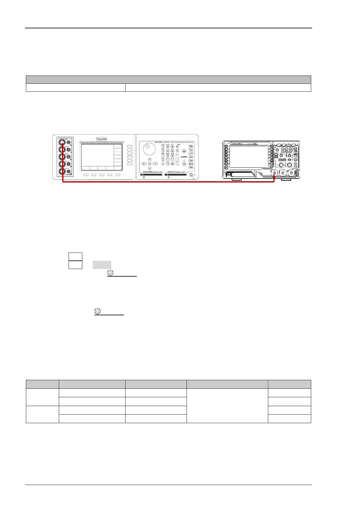
Figure 2-1 Impedance Test Connection Diagram
Test Procedures
1. Connect the active head of Fluke 9500B to CH1 of the oscilloscope, as shown in the figure above.
2. Configure the oscilloscope:
1) Press CH1 in the vertical control area (VERTICAL) on the front panel to turn on CH1.
2) Press CH1 Probe to set the probe attenuation ratio to "1X".
3) Rotate VERTICAL SCALE to set the vertical scale of CH1 to 100 mV/div.
3. Turn on Fluke 9500B; set its impedance to 1 MΩ and select the resistance measurement function.
Read and record the resistance measured.
4. Rotate VERTICAL
SCALE to adjust the vertical scale of CH1 of the oscilloscope to 500
mV/div; read and record the resistance measured.
5. Turn off CH1. Measure the resistance of CH2 using the method above and record the
measurement results.
Test Record Form
CH1
0.99 MΩ to 1.01 MΩ
CH2
 Loading...