Chapter 2 Performance Verification Test RIGOL
DS1000Z-E Performance Verification Guide
Time Base Accuracy Test
Specification
Specification
≤ ±(25 ppm + Clock Drift
[2]
×Number of years that the instrument has
been used
[3]
)
Note
[1]
: Typical.
Note
[2]
: Clock drift is lower than or equal to ±5 ppm/year.
Note
[3]
: For the number of years that the instrument has been used, please calculate according to the date in the
verification certificate provided when the instrument leaves factory.
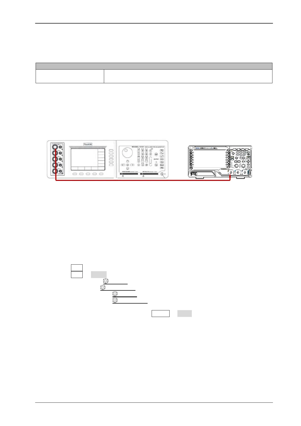
Test Connection Diagram
Figure 2-5 Time Base Accuracy Test Connection Diagram
Test Procedures
1. Connect the active head of Fluke 9500B to CH1 of the oscilloscope, as shown in the figure above.
2. Turn on Fluke 9500B and set its impedance to 1 MΩ.
3. Output a Sine with 10 MHz frequency and 1.2 Vpp amplitude via Fluke 9500B.
4. Configure the oscilloscope:
1) Press CH1 in the vertical control area (VERTICAL) on the front panel to turn on CH1.
2) Press CH1 Probe to set the probe attenuation ratio to "1X".
3) Rotate VERTICAL SCALE to set the vertical scale to 200 mV/div.
4) Press VERTICAL POSITION to set the vertical position to 0.
5) Rotate HORIZONTAL SCALE to set the horizontal time base to 10 ns/div.
6) Rotate HORIZONTAL POSITION to set the horizontal position to 1 ms.
5. Observe the screen of the oscilloscope. Press Cursor Mode "Manual" to turn on the manual
cursor function. Measure the offset (ΔT) of the middle point of the signal (namely the crossing
point of the rising edge of the current signal and the trigger level line) relative to the screen center
using manual cursor measurement and record the measurement result.
6. Calculate the time base accuracy; namely the ratio of ΔT to the horizontal position of the
oscilloscope. For example, if the offset measured is 1 ns, the time base accuracy is 1 ns/1 ms=1
ppm.
7. Calculate the time base accuracy limit using the formula "±(25 ppm + 5 ppm/year × number of
years that the instrument has been used).
 Loading...