Chapter 2 Performance Verification Test RIGOL
DS1000Z-E Performance Verification Guide
DC Gain Accuracy Test
Specification
Specification
< 10 mV: ±4% × Full Scale
[1]
≥ 10 mV: ±3% × Full Scale
[1]
Note
[1]
: Full Scale = 8 × Current Vertical Scale
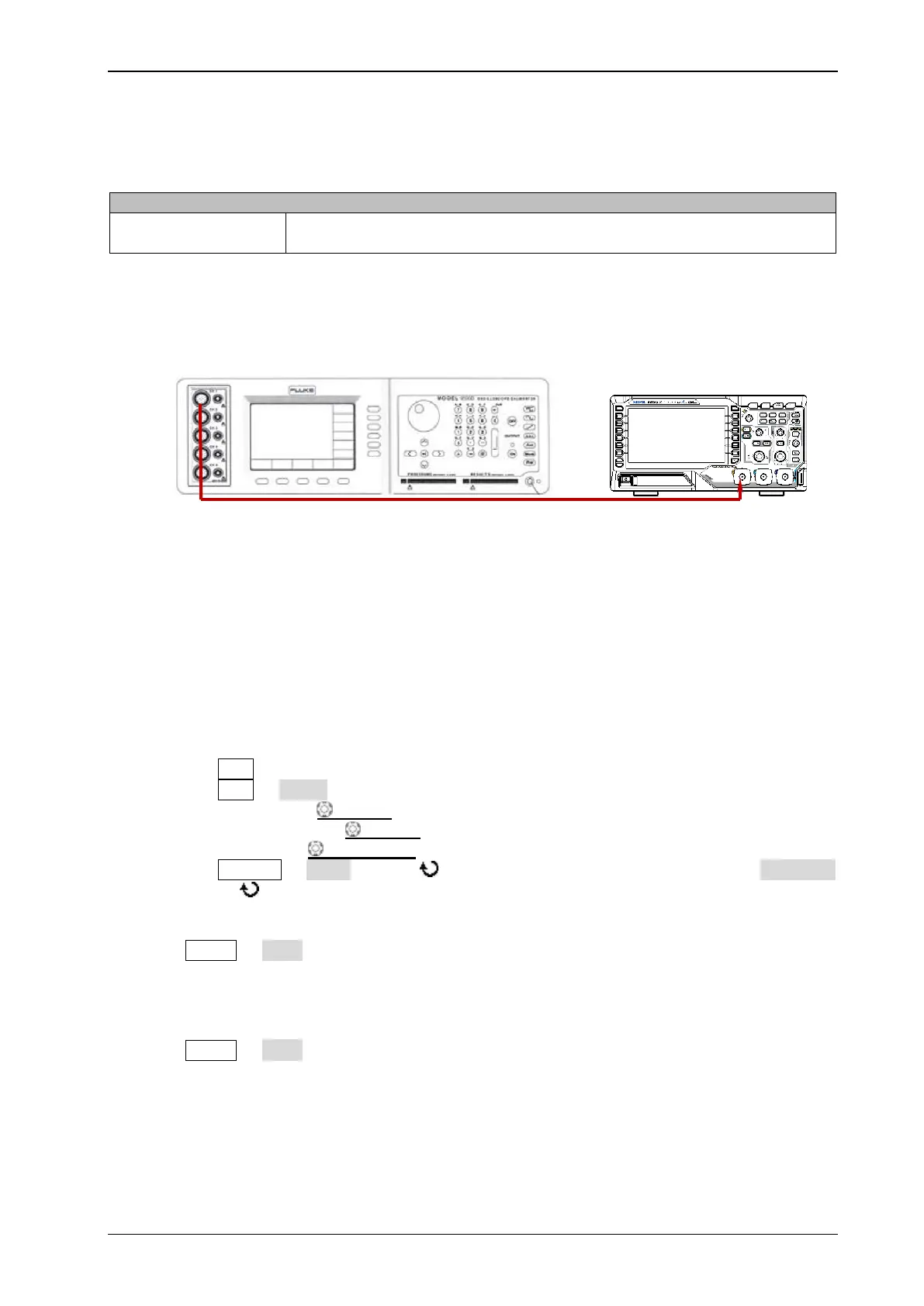
Test Connection Diagram
Figure 2-2 DC Gain Accuracy Test Connection Diagram
Test Procedures
1. Connect the active head of Fluke 9500B to CH1 of the oscilloscope, as shown in the figure above.
2. Turn on Fluke 9500B and set its impedance to 1 MΩ.
3. Output a DC signal with +3 mV
DC
voltage (Vout1) via Fluke 9500B.
4. Configure the oscilloscope:
1) Press CH1 in the vertical control area (VERTICAL) on the front panel to turn on CH1.
2) Press CH1 Probe to set the probe attenuation ratio to "1X".
3) Rotate VERTICAL SCALE to set the vertical scale to 1 mV/div.
4) Rotate HORIZONTAL SCALE to set the horizontal time base to 100 us/div.
5) Press VERTICAL POSITION to set the vertical position to 0.
6) Press Acquire Mode and use to select "Average" acquisition mode; press Averages
and use to set the number of averages to 32.
7) Adjust the trigger level to avoid that the signals are being triggered by mistake.
5. Press MENU Vavg at the left side of the screen of the oscilloscope to turn on the average
measurement function. Read and record Vavg1.
6. Adjust Fluke 9500B to make it output a DC signal with -3 mV
DC
voltage (Vout2).
7. Press MENU Vavg at the left side of the screen of the oscilloscope to turn on the average
measurement function. Read and record Vavg2.
8. Calculate the relative error of this vertical scale: |(Vavg1 - Vavg2) - (Vout1 - Vout2)|/Full
Scale × 100%.
9. Keep the other settings of the oscilloscope unchanged:
1) Set the vertical scale to 2 mV/div, 5 mV/div, 10 mV/div, 20 mV/div, 50 mV/div, 100 mV/div,
 Loading...