MerCruiser PCM-555 EFI
Page 37
PCM System Info
e PCM-555 control module contains an area of memory that is used to store
helpful text information for a service technician. is information consists of
many lines of text which describe basic engine settings, capacities, etc, as well
as PCM soware revision information. e System Info data is entered into the
PCM’s memory at the factory and may be accessed as follows:
Aer selecting the “PCM System Info“ option from the main PCM menu the
scanner will begin uploading the system information. A bar graph indicator will
be displayed indicating the scan tool’s progress.
Once the system information is uploaded into the scan tool’s memory it will be
displayed. Use the ▲ and ▼ keys to scroll through the information. Press the
NO key to return to the main PCM menu.
PCM Functions
e PCM Functions menu option allows a technician to access a variety of PCM
functional tests and settings as shown in Figure 18.
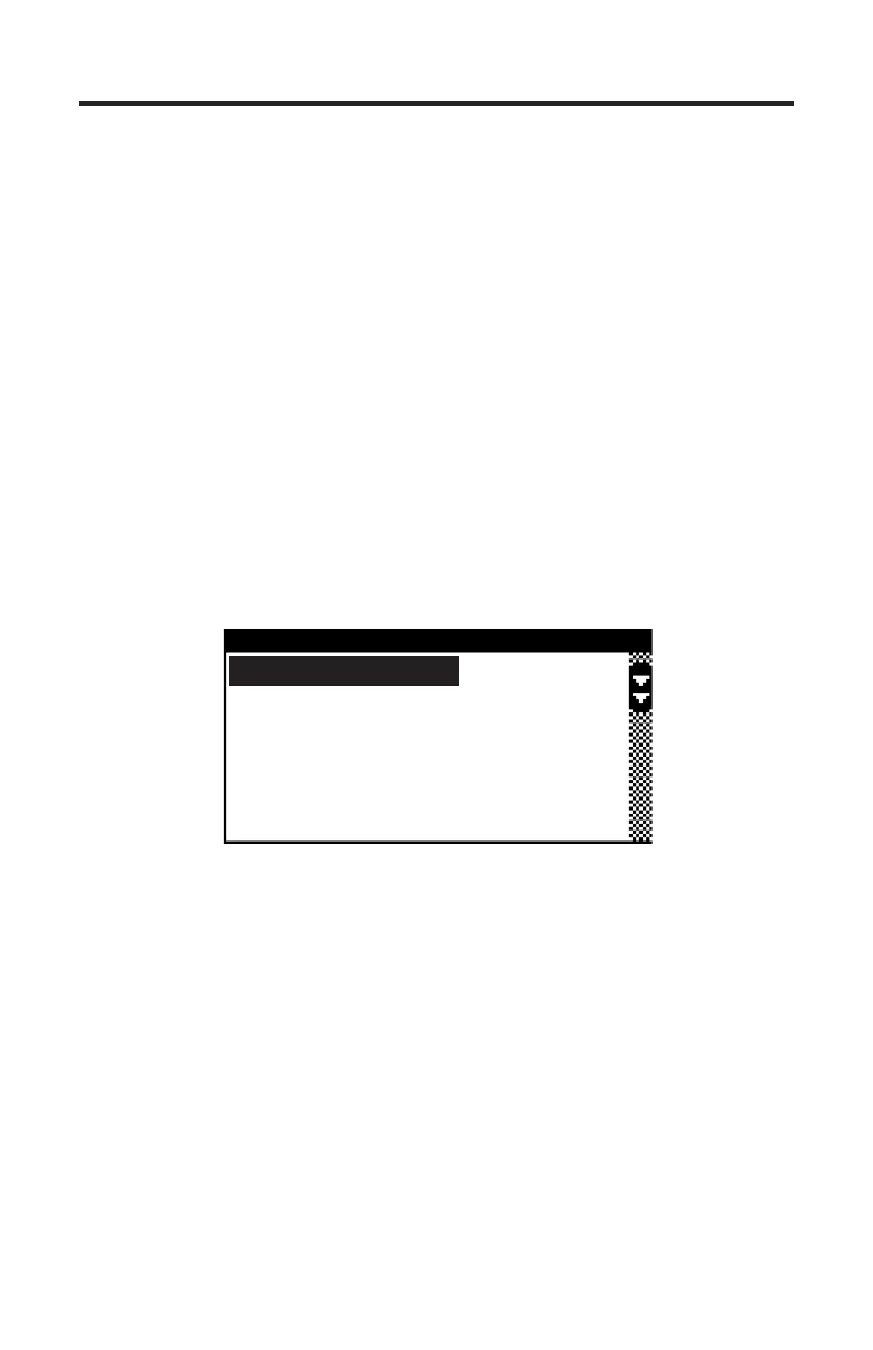
Figure 18 PCM Functions Menu
PCM FUNCTIONS
Output Tests
Induced Misfire Test
Set Engine Location
Set Trim Limit
Set Trailer Limit
Output Tests
e Output Test menu option provides a technician with the ability to exercise
various PCM actuators and controls in order to verify correct operation. Select-
ing the “Output Tests” menu choice displays a sub-menu of items available as
shown in Figure 19.
Supported output tests will dier based upon the type of engine you are ser-
vicing. Some items apply only to engines equipped with DTS (digital throttle
and shi) for example. An engine equipped with sequential fuel injection will
support the ring of individual fuel injectors whereas an engine equipped with
an ECM-555 system, which is bank-red, will not support individual injector
ring. Always refer to the engine manufacturer’s service manual for details on
the specic output tests available on the engine you are servicing.