8
Rinnai Corporation Hydronic Air Handler Manual
IMPORTANT: When a 37AHA unit is matched with an
evaporative type (cased coil/condensing unit) split
system for cooling application and the system is
installed above a finished ceiling and/or an occupied
space, building codes may call for a secondary
insulated condensate pan (by others) to be installed
under the entire unit. In other instances, some local
codes may allow the running of a separate, secondary
condensate line in lieu of the required drain pan. It is
the responsibility of the installer to consult local codes
for compliance.
It is the installer’s responsibility to use an appropriate
hanging method capable of supporting the unit’s
weight. Refer to the specification section of this
document for the respective unit’s installed weights.
WARNING
Installation
CLOSET INSTALLATION (RETURN AIR THRU
OPENING OR GRILL)
The 37AHA Hydronic Air Handler can be installed in a
closet on a supporting stand or be mounted from the
closet wall using the closet as the return air plenum.
Unit should be high enough from the floor to provide
unimpeded return air flow into the bottom of the
cabinet.
Closet return air opening can be on the front (in closet
door), side (thru the wall) or a combination of both,
providing there is clearance on the sides between
unit’s cabinet and closet. Refer to ACCA Manual D or
SMACNA for sizing and free area recommendations.
NOTE: Local codes may limit application of systems
without a ducted return to single story dwellings.
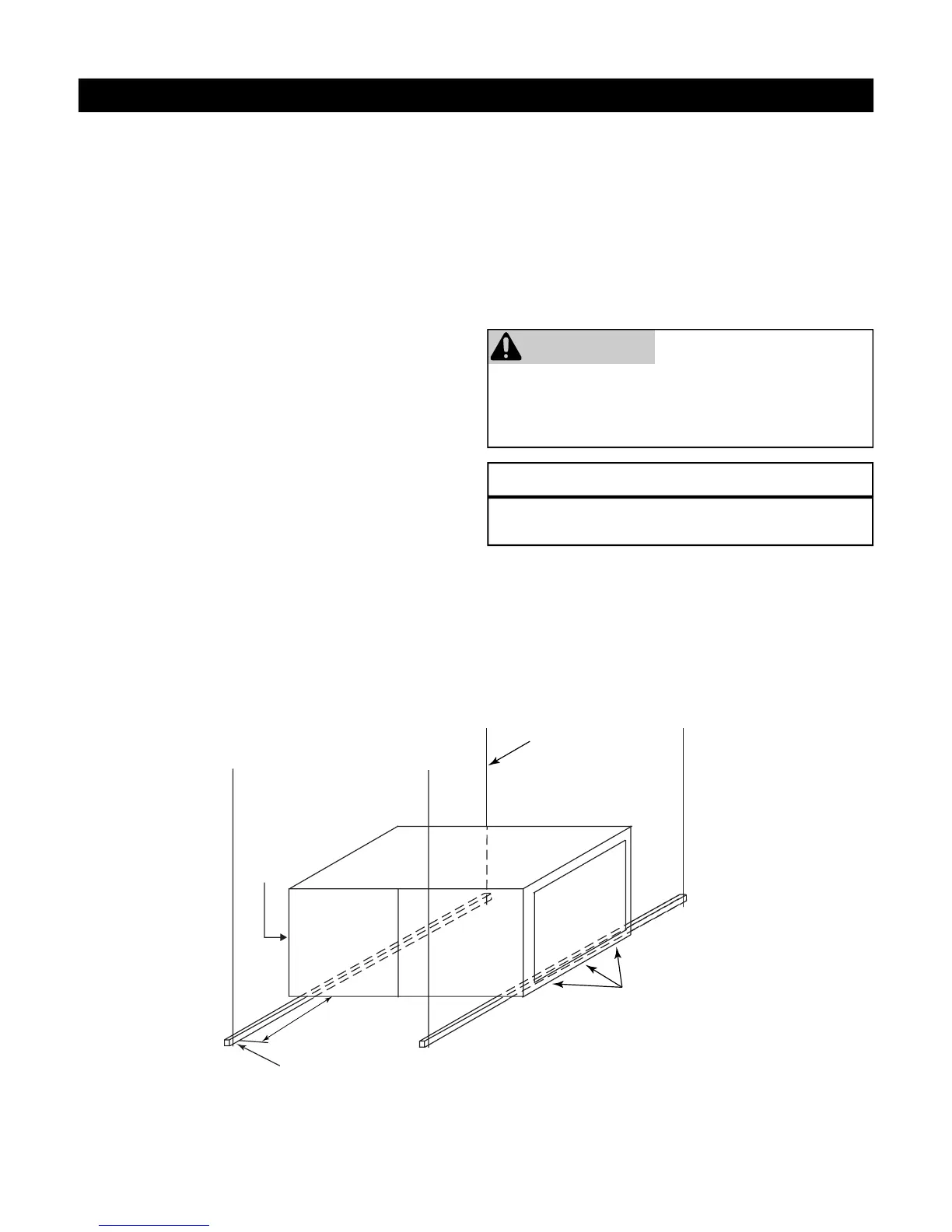
DOOR
ASSEMBLY
8” MIN FOR
DOOR REMOVAL
(2) HEX NUTS, (2) WASHERS & (2)
LOCK WASHERS REQ. PER ROD
USE 1” SQUARE, 1-1/4 x 1-1/4 x 1/4
ANGLE IRON OR EQUIVALENT
SECURE ANGLE
IRON TO BOTTOM
OF AIR HANDLER
WITH 3 #8 x 3/4”
SCREWS TYPCIAL
FOR 2 SUPPORTS
1/4” THREADED ROD
(4 REQUIRED)
Figure 6: Horizontal Unit Suspension
SUSPENDED CABINET INSTALLATION
If the cabinet cannot be supported on a frame or
supported from the wall, it may be suspended.
Use metal strapping or threaded rod with angle iron
supports under cabinet for support. These supports
MUST run parallel with the length of the cabinet (see
Figures 6 and 7).
Ensure that there is adequate room to remove service
and access panels after installing supporting brackets.
If an auxiliary drain pan is required, the support is to
be placed under a drain pan. In such installations the
unit will need to be supported on vibration isolators
(rubber or Styrofoam blocks).
For seismic hanging requirements, refer to local
codes.
NOTICE
 Loading...