Do you have a question about the Rinnai RHFE-556FTD and is the answer not in the manual?
Indicates when the fan filter is blocked and requires cleaning. Located on the appliance.
Allows adjustment of airflow direction by bending louvres left or right using a tool.
Integral tray to raise humidity level in the room. Filled with water.
Automatically stops appliance after a fixed time period (1-12 hours) for energy saving.
Micro-computer records preset temperatures for comfort level maintenance.
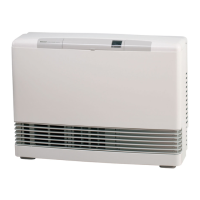
Instructions on how to open the control panel cover using a finger.
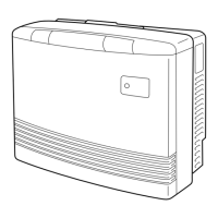
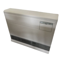
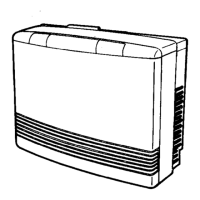
Steps to turn on the heater, indicators, and initial ignition process.
Procedure for switching off the heater and the convection fan's cooling process.
Checks to perform when the heater does not operate or fails to ignite.
Checks for issues like clunking noise, unit not heating, or blocked louvres.
Checks related to the convection fan continuing to run after the unit is turned off.
Checks for issues like steam discharge or unit cutting off without reason.
Guidance on flue placement and clearances, avoiding flammable materials.
Ensuring combustible materials do not contact the heater and managing curtain proximity.
Specifies Rinnai flue kits, external flue terminals, and placement near opening windows.
Lists available flue lengths (AA, A, B, C, D, E) and coaxial flue options.
Advice for snow areas to keep flue terminals clear of snow.
Diagrams showing minimum clearances and distances for flue manifold installation.
Details required side clearances from flammable and non-flammable walls.
Instructions on fitting back covers (sides only) using screws and lugs.
Guidance on fitting a suitable copper flare elbow to the appliance inlet.
Advises against installing the heater in unusually dusty areas.
Instructions for drilling through weatherboard walls for flue installation.
Recommends using a flue guard if the terminal is accessible to children.
Requirement for the floor to be level for proper installation.
Prohibits using electrical extension cords and specifies keeping the power cord away from the flue.
Guidance on positioning the flue manifold within a shaded area to avoid studs.
Detailed steps for positioning and attaching wall mounting brackets for the heater.
Procedure to disassemble the manifold from the sleeve and its components.
Measuring wall thickness and adjusting sleeve length to protrude 5-10mm from the wall.
Instructions for removing extension piece 'C' for specific flue types.
Securing the sleeve to the wall using provided screws, ensuring correct orientation.
Verifying the rubber seal is correctly placed on the terminal, with an option for weatherboard walls.
Inserting the terminal into the sleeve, aligning marks and fixing ties.
Pulling and clipping ties over lugs inside the sleeve, cutting excess, and bending them.
Pushing the inner connection assembly into the terminal tube and securing with screws.
Note that the manifold can be turned after attachment.
Steps for connecting the air inlet hose, including detail of hose clip.
Fitting locking clamp, screw clamp, and insulation sleeve to the flue/manifold.
Connecting the flue outlet to the manifold by extending the sliding tube fully.
Fitting the locking clamp over the connection between the sliding tube and manifold.
Securing the sliding tube and flue elbow using the screw clamp.
Sliding the insulation sleeve up to the flue manifold and securing it with a clip.
Detailed steps for checking gas pressure at low and high settings using a gauge.
Step-by-step guide to re-setting low and high gas pressures using control panel buttons.
Clipping top spacer into wall brackets and securing with screws to fix heater to wall.
Using adjustable legs to level the unit if necessary.
Explaining heater operation to the customer once it's confirmed to be working correctly.
Procedure to follow if the heater cannot be operated correctly after installation.