Installation and Programming Manual
2-4
I
I
d
d
e
e
n
n
t
t
i
i
f
f
y
y
i
i
n
n
g
g
a
a
n
n
d
d
W
W
i
i
r
r
i
i
n
n
g
g
K
K
e
e
y
y
p
p
a
a
d
d
s
s
a
a
n
n
d
d
E
E
x
x
p
p
a
a
n
n
s
s
i
i
o
o
n
n
M
M
o
o
d
d
u
u
l
l
e
e
s
s
(refer to Figures 2-2, 2-3, 2-5, and 2-6: found on pages 2-9, 2-10, 2-11, and 2-11, respectively)
Prepare each Keypad(s) and Expansion Module(s) you plan to install according to the information found
in the table below:
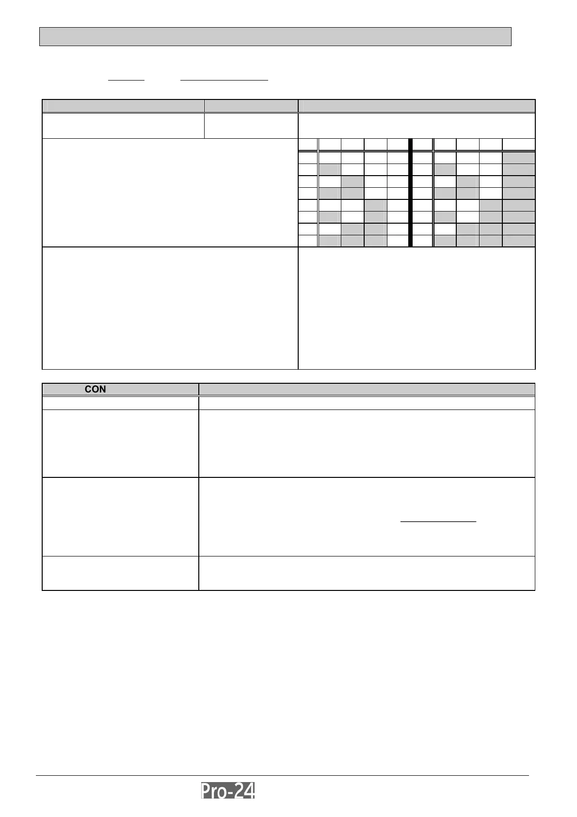
COMPONENT/MODULE AREA COMMENTS
Keypads and
Expansion Modules
DIP Switches
Program each device’s I.D. number by setting its
DIP switches accordingly, as described:
ID 1 2 3 4 ID 1 2 3 4
01 off off off off 09 off off off ON
02 ON off off off 10 ON off off ON
03 off ON off off 11 off ON off ON
04 ON ON off off 12 ON ON off ON
05 off off ON off 13 off off ON ON
06 ON off ON off 14 ON off ON ON
07 off ON ON off 15 off ON ON ON
Each Keypad and Expansion Module must be given a
unique I.D. number with which it is identified in the
system. Use the instructions below, along with the table at
the right, to set the DIP switches on the device’s PC
board.
08
ON ON ON off 16 ON ON ON ON
Keypads:
Remove the keypad’s back cover in order to set up
its ID.
The first keypad must be given I.D. 01, the second,
I.D. 02, etc. For convenience during the installation
and programming, you might want to temporarily
label each keypad’s I.D. on its face.
Expansion Modules:
As above; however, there is no cover to remove
It is normal for the same sequence of I.D. numbers to
be repeated for different types of devices (i.e.
Keypads and Expansion Modules) used in the
system. Thus, the I.D. of “01” must be used for the
first Keypad, the first Zone Expander, the first Utility
Output, and first Power Supply Module. A second
module in any of these categories gets the I.D. of
“02”, etc.
CONNECTIONS COMMENTS
DIP Switches
each Keypad must be given a unique I.D. number see above
Bus Wiring
AUX (Red) COM (Blk)
BUS (Yel) BUS (Grn)
extend the four wires within each keypad as required, and connect
each to the appropriate point, either to the panel's Expansion Bus
terminals, to the BUS terminals of another Expansion Module, to a
"splice box", or to any other suitable point on the BUS
for very long wire runs, use the appropriate wire gauge (22-19) to avoid
excessive voltage drops (see page 2-8)
Tamper Switch
refer to Figure 2-3 on page 2-10 and set the keypad’s Tamper Switch
as follows:
- locate the rear-mounted tamper “plunger”; if the keypad is to be wall-
mounted, be sure the slot in the plunger is vertically-oriented
before
mounting the keypad
- if the keypad is not to be mounted at this time, the plunger’s position can
be ignored
Cover
carefully replace the keypad’s printed circuit board in its cover; next,
join the cover and base by first hooking the tops together and then
snapping the bottom in place