Installation and Programming Manual
2-6
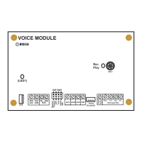
Wiring the Power Supply Expansion Module
CONNECTIONS COMMENTS
DIP Switches
each Power Supply (Expansion) Module must be given a unique
I.D. number identifying it to the system; use the table on page 2-4 to set
the DIP switches appropriately
Bus Terminals
AUX (Red) COM (Blk)
BUS (Yel) BUS (Grn)
the first four terminals at the left of the Power Supply Module are for the
connection to the Expansion Bus, originating at the Main Board
because the Power Supply Module has its own source of power-derived
through its connection to AC Power-do NOT connect the RED wire from
the Expansion Bus to the module; connect only the black, yellow, and
green wires from the bus to the appropriate BUS terminals (see Figure 2-6
on page 2-11)
from the point at which the Power Supply Module is wired to the BUS, it
will supply power to all modules and/or keypads located AFTER its
connection; as such, do NOT make any connections to the disconnected
RED wire cited above
the maximum wire run permitted is 1000 feet for all legs of the BUS
Tamper
TAMP COM
if the Power Supply Module is enclosed in a metal cabinet and it’s desired
to "tamper" the cabinet, connect one (or more) appropriate normally-open
momentary-action pushbutton switch(es), in series, between the TAMP
and COM terminals
it is NOT necessary to use a tamper switch if another module sharing the
same metal cabinet is so equipped
do NOT use an End-of-Line Resistor in the tamper switch circuit
if a tamper switch is NOT used, connect a wire jumper between the two
terminals
External Sounders
BELL/LS
+ –
connect suitable wire to any additional external sounding device(s)–
whether a bell, an electronic siren, or a loudspeaker–that you want to be
part of the system and, for convenience, driven by the Power Supply
Expansion Module
consider a large wire gauge (e.g. 18-16) if the distance separating the
sounder and the module is significant; consider, too, the sounder’(s)
current draw when choosing a suitable wire gauge (see page 2-7 for
additional information)
any external sounder(s) connected to the Power Supply Module will
operate exactly like the sounder(s) connected to the Main Board
BELL/LS
Jumper
be sure to appropriately position the board's BELL/LS Jumper, as follows
- if your external sounder is a Loudspeaker
(without a built-in sound driver),
position the BELL/LS jumper so it covers both pins; doing so causes the
Power Supply Module to produce a continuous oscillating voltage for
burglary/panic alarms, and an interrupted oscillating voltage for fire alarms
- if your external sounding device is either a Bell
or an Electronic Siren
(equipped with a built-in sound driver), position the jumper so it does NOT
cover both pins; as such, a steady 12 Volts DC is produced at the sounder
terminals during burglary/panic alarms; a slow, pulsing voltage is produced
during a fire alarm
Power to Auxiliary Device
AUX COM
(+) (–)
for auxiliary devices whose location is too far from the panel, wire these
terminals to power PIRs, glass-break detectors (4-wire types), audio
switches, photoelectric systems, and any device whose operation requires
a continuous supply of 12 Volts DC see Figure 2-5 on page 2-11)
wire should be of a suitable gauge to accommodate any voltage drop
which might occur based on current requirements and distance involved
AC
wire the output from a 16.5 VAC, 40 VA transformer to the board’s AC
terminals
use the appropriate wire gauge (see page 2-7 for additional information)
do NOT plug in the transformer at this time
Flying Leads
RED and BLACK
at the proper time, connect these leads to the positive (+) and negative (–)
terminals, respectively, of the appropriate Standby Battery used with the
Power Supply Module