Rittal enclosure cooling unit 11
4 Assembly and connection
EN
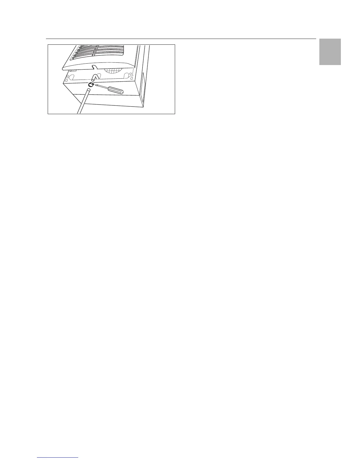
Fig. 19: Connecting the condensate discharge
Connect a suitable hose to the condensate nozzle and
secure using a hose clip.
Route the condensate hose to a drain or into the ex-
ternal condensate evaporator (refer to Accessories in
the Rittal Catalogue).
4.5 Notes on electrical installation
When performing the electrical installation, it is important
to observe all valid national and regional regulations as
well as the provisions of the responsible power supply
company. The electrical installation may only be carried
out by a qualified electrician who is responsible for com-
pliance with the applicable standards and regulations.
4.5.1 Connection data
– The connected voltage and frequency must corre-
spond to the values stated on the rating plate
– The cooling unit must be connected to the mains via
an all-pin isolating device, which ensures at least
3 mm contact opening when switched off
– No additional temperature control may be connected
upstream of the unit at the supply end
– Install the protective device specified on the rating
plate to protect the line and equipment from short-cir-
cuits.
– The mains connection must ensure low-noise poten-
tial equalisation
4.5.2 Overvoltage protection and supply line load
– The unit does not have its own overvoltage protection.
Measures must be taken by the operator at the supply
end to ensure effective lightning and overvoltage pro-
tection. The mains voltage must not exceed a toler-
ance of ±10%.
– In accordance with IEC 61 000-3-11, the unit is in-
tended solely for use at sites with a continuous cur-
rent-carrying capacity (incoming mains power supply)
of more than 100 A per phase and with a supply volt-
age of 400/230 V. If necessary, the electricity supply
company must be consulted to ensure that the contin-
uous current-carrying capacity at the point of connec-
tion to the public grid is sufficient for connection of
such a unit.
– The fans and compressors in single- and three-phase
units are intrinsically safe (thermal winding protection).
This also applies to transformer versions, types
3304.510, 3305.510, 3328.510 and 3329.510, and to
special-voltage units which are likewise equipped with
a transformer.
– Install the protective device specified on the rating
plate to protect the line and equipment from short-cir-
cuits (miniature circuit-breaker with appropriate char-
acteristic – e.g. "K" characteristic – or gG standard
type slow fuse, circuit-breaker for plant or transformer
protection). Select a suitable circuit-breaker in accord-
ance with the information specified on the rating plate:
Set it to the minimum specified value. This will achieve
the best short-circuit protection for cables and equip-
ment. Example: Specified setting range 6.3 – 10 A; set
to 6.3 A.
4.5.3 Three-phase devices
– The electrical connection for devices in the three-
phase version MUST be made with a clockwise rotat-
ing field
– The three-phase version of models 3304.xxx,
3305.xxx, 3328.xxx, 3329.xxx and 3332.xxx must be
connected to a TN network with star earthing via a cir-
cuit-breaker for plant protection (current setting as per
the rating plate). Three-phase units with special volt-
ages must be protected with a circuit-breaker for
transformer protection (category AC-3) as per the rat-
ing plate.
– Units designed for three phase 400/460 V feature ad-
ditional monitoring of the rotary field or the absence of
a phase. If the rotary field is incorrect or a phase is ab-
sent, the unit will not run.
4.5.4 Door limit switch
– Each door limit switch must only be assigned to one
cooling unit.
– Several door limit switches may be connected in par-
allel to one cooling unit.
– The minimum cross-section for the connection cable
is 0.3 mm
2
for a cable length of 2 m.
– The line resistance to the door limit switch must not
exceed a maximum of 50 .
– The door limit switch only supports a floating connec-
tion; no external voltages.
– The contact of the door limit switch must be closed
when the door is open.
The safety extra-low voltage for the door limit switch is
provided by the internal power pack: Current approx.
30 mA DC.
Connect the door limit switch to terminals 1 and 2 of
the connector.
4.5.5 Notes on the flicker standard
The flicker limits specified in standard EN 61 000-3-3 or
-3-11 are adhered to, provided the supply impedance is
less than approx. 1.5 .
Where necessary, the unit operator should measure the
connected impedance or consult the responsible elec-
tricity supply company. If there is no way of influencing
 Loading...