4 Assembly and connection
EN
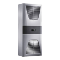
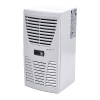
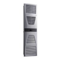
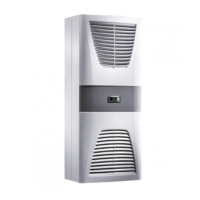
6 Rittal enclosure cooling unit
er fan and compressor switch on after approximately
3minutes.
3.2.8 Additional interface X3
An additional interface card may be connected to the 9-
pole SUB-D connector X3 in order to incorporate the
cooling unit into higher-level monitoring systems (availa-
ble as an accessory, interface card Model No.
3124.200).
3.3 Proper use, foreseeable misuse
The cooling unit is only intended for cooling connected
enclosures. Any other use is not permitted.
– The unit must not be installed and operated in loca-
tions which are accessible to the general public (see
DIN EN 60335-2-40, paragraph 3.119).
– The unit is designed solely for stationary use.
The cooling unit is state of the art and built according to
recognised safety regulations. Nevertheless, improper
use can pose a threat to the life and limb of the user or
third parties, or result in possible damage to the system
and other property.
Consequently, the cooling unit must only be used prop-
erly and in a technically sound condition! Any malfunc-
tions which impair safety should be rectified immediate-
ly.
Proper use also includes the observance of the docu-
mentation provided, and compliance with the inspection
and maintenance conditions.
Rittal GmbH & Co. KG is not liable for any damage which
may result from failure to comply with the documenta-
tion provided. The same applies to failure to comply with
the valid documentation for any accessories used.
Inappropriate use may be dangerous. Examples of inap-
propriate include:
– Use of the cooling unit over long periods with the en-
closure open.
– Use of impermissible tools.
– Improper operation.
– Improper rectification of malfunctions.
– Use of accessories not approved by Rittal GmbH &
Co. KG.
3.4 Scope of supply
The unit is supplied in a packaging unit in a fully assem-
bled state.
Please check the scope of supply for completeness.
4 Assembly and connection
4.1 Choosing the installation site
When choosing the installation site for the enclosure,
please observe the following:
– The site for the enclosure, and hence the arrangement
of the cooling unit, must be carefully selected so as to
ensure good ventilation (clearance between units and
clearance between the unit and the wall must be at
least 200 mm in each case).
– The cooling unit must be installed and operated in a
vertical position (maximum deviation: 2°).
– The installation site must be free from excessive dirt,
aggressive ambient conditions and moisture.
– The ambient temperature must be within the limits
specified on the rating plate.
– It must be possible to fit a condensate discharge (see
section4.4 "Connecting the condensate discharge").
– The mains connection data as stated on the rating
plate of the unit must be guaranteed.
4.2 Notes on assembly
4.2.1 General
– Check the packaging carefully for signs of damage.
Traces of oil on damaged packaging are an indication
of refrigerant loss and leakages. Any packaging dam-
age may be the cause of a subsequent functional fail-
ure.
– The enclosure must be sealed on all sides (IP 54). In-
creased condensation will occur if the enclosure is not
airtight.
– In order to avoid excessive condensation inside the
enclosure, we recommend installing a door limit
switch (e.g. 4127.010) which deactivates the cooling
unit when the enclosure door is opened (see sec-
tion3.2.7 "Door limit switch").
Note:
– No external voltage may be applied to the
door contacts (terminals 1 and 2).
– For cooling units with basic control, the
evaporator fan continues to run even
when the door is open.
Note:
The electrical signals at the interface are of
an extra-low voltage (not extra-low safety
voltages to EN 60 335).
Qty. Description
1 Enclosure cooling unit
1
1
1
1
4 – 10
Dispatch bag:
– Assembly and operating instructions
–Self-adhesive tape
– Connector X1
–Grub screws
– Nuts, washers
1 Drilling template
Tab. 1: Scope of supply
 Loading...