4 Assembly and connection
EN
12 Rittal enclosure cooling unit
the supply impedance and sensitive installed compo-
nents (e.g. BUS) are subjected to interference, a line re-
actor or starting-current limiting device should be con-
nected upstream of the cooling unit to restrict the start-
up current of the cooling unit.
4.5.6 Potential equalisation
If, for EMC reasons, the unit is to be integrated into the
customer’s existing potential equalisation system, a
conductor with a larger nominal cross-section can be
connected to the potential equalisation connection point
(attachment points) on the wall-mounted cooling units.
According to the standard, the PE conductor in the
mains connection cable is not classified as an equipo-
tential bonding conductor.
4.6 Making the electrical connection
4.6.1 Bus connection
(only when interconnecting several units
with a Comfort controller)
When using several cooling units, the serial device inter-
face X2 can be used to connect up to ten cooling units
with the bus cable (Model No. 3124.100).
When interconnecting, please note the following:
– De-energise the cooling units to be connected
– Ensure proper electrical insulation
– Make sure the cables are not laid in parallel to power
lines
– Make sure that the lines are short
4.6.2 Connection X3 for serial interface
The interface card (Model No. 3124.200) may be con-
nected to X3. This is used to evaluate system messages
in a PLC, for remotely setting parameters and monitor-
ing, or for integration into the facility management sys-
tem.
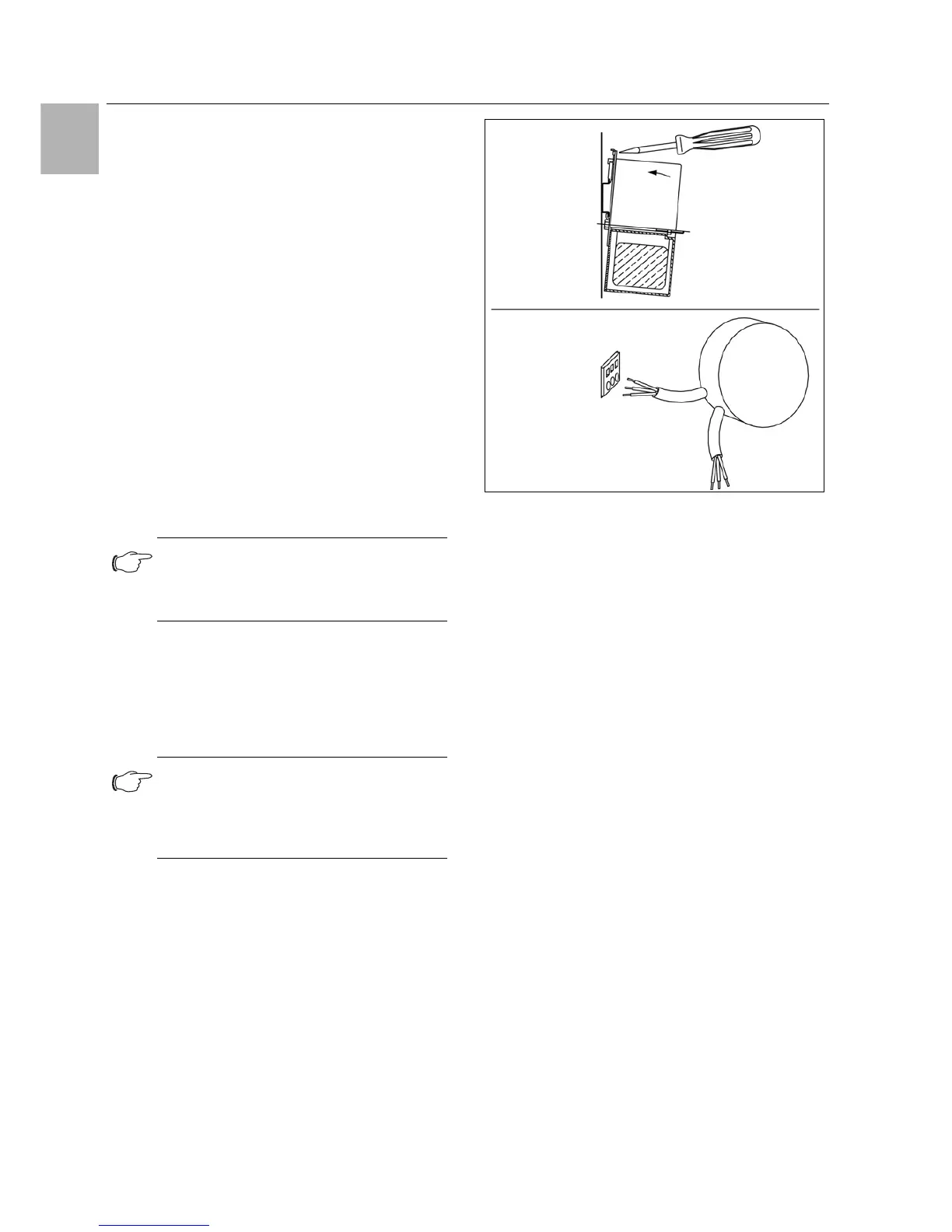
4.6.3 Mounting external transformer
Only for 3361.x40.
Fig. 20: Mounting external transformer (3361.x40 only)
Note:
The electrical signals at the X2 interface are
of an extra-low voltage (not extra-low safety
voltages in accordance with EN 60 335-1).
Note:
With the last slave unit in the group, do not,
under any circumstances, connect the re-
maining socket of the Y cable 3124.100 into
interface X3 of the cooling unit!
 Loading...