4 Assembly and connection
EN
8 Rittal enclosure cooling unit
4.3.1 Making the cut-outs
Affix the supplied drilling template to the side panel or
door of the enclosure using adhesive tape.
There are dimensioning lines on the drilling template to
suit the various installation options for your cooling unit.
Using the dimension drawings (see Appendix), identify
the valid lines and dimensions for your installation type
on the drilling template.
Mark, drill and deburr the holes.
Make the cut-outs including the line width as per the
drilling template.
Deburr the cut-outs.
4.3.2 External mounting of the cooling unit
Cut the supplied sealing tape to the correct length and
stick it carefully along the back of the unit so that no
gaps are left at the joints.
Fig. 7: Applying the self-adhesive tape
Screw the supplied grub screws into the blind nuts on
the rear of the unit.
Secure the unit using the supplied washers and nuts.
Fig. 8: Securing the cooling unit (all models except 3302.1xx)
Fig. 9: Securing the cooling unit (3302.1xx only "external
mounting")
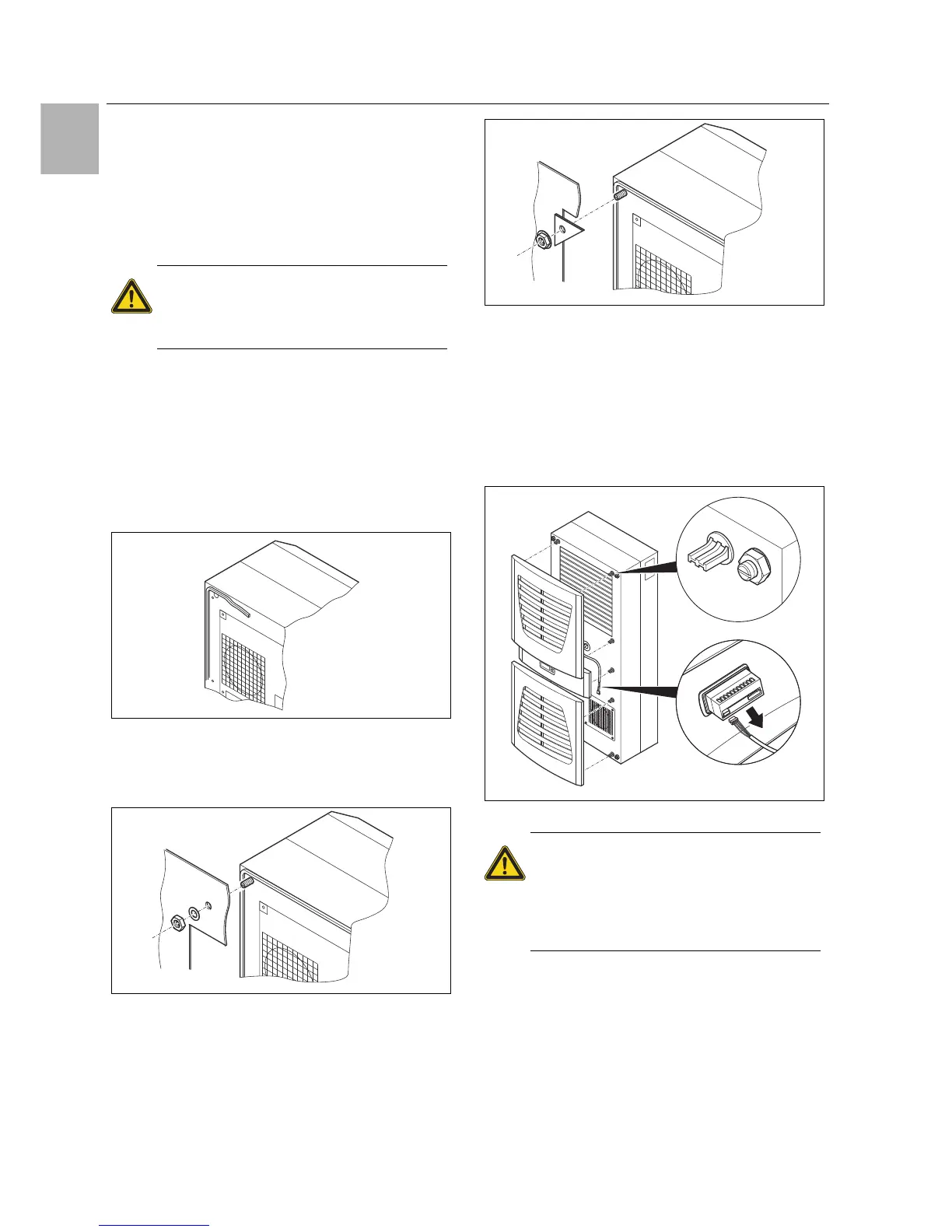
4.3.3 Partial internal mounting of the cooling unit
Carefully remove the louvred grille and, where applica-
ble, the infill panel, from the enclosure by pulling for-
wards.
Carefully disconnect the connector from the rear of the
display and gently push it inwards through the cable
gland.
Fig. 10: Removing the louvred grille & disconnecting the display
Loosen the four nuts on the front half of the enclosure
and pull the enclosure forwards by approx. 5 cm.
Loosen the flat-pin connectors of the PE conductor
between the two enclosure halves.
Disconnect the fan connection.
Remove the front enclosure tray completely.
Caution!
Carefully deburr all drilled holes and
cut-outs to prevent injuries caused by
sharp edges.
Caution!
Stability of the cooling unit is only guar-
anteed in its assembled state. Brace
the rear half of the enclosure to prevent
it from falling over before removing the
front half.
 Loading...