3 Device description
EN
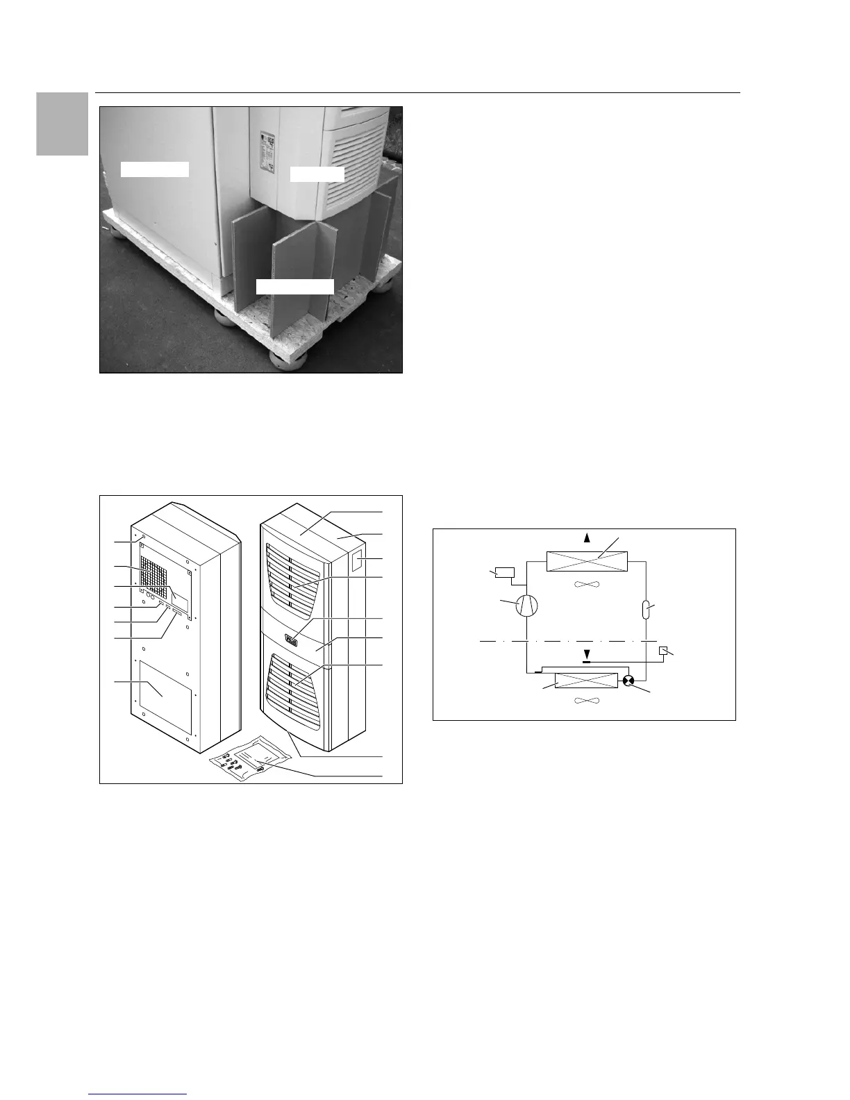
4 Rittal enclosure cooling unit
Fig. 1: Transporting an enclosure/cooling unit combination
3 Device description
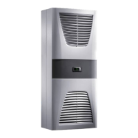
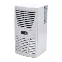
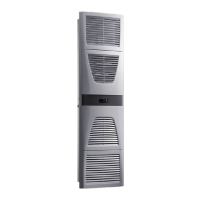
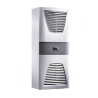
Depending on the model chosen, your cooling unit may
vary in appearance from the illustrations contained in
these instructions. However, the functions are identical
in principle.
Fig. 2: Device description
Key
1 Blind rivet nut
2Evaporator fan
3 Electrical wiring plan
4 X2 master-slave connection
5 X3 optional serial interface
6 X1 terminal strip
7 Air outlet hole
8 Front half of the enclosure
9 Rear half of the enclosure
10 Louvred grille for air outlet
11 Display
12 Infill panel
13 Louvred grille for air inlet
14 Rating plate
15 Condensate discharge
16 Dispatch bag
3.1 TÜV-tested output measurement to
DIN EN 14511
All TopTherm cooling units in the output range from 300
to 4000 W are tested to the latest EN 14511-1-4:2013-
12 standard by independent test institute TÜV Nord.
This means you have peace of mind about the design of
the climate control solution and you can be sure you are
getting the performance you are paying for.
3.2 Functional description
3.2.1 How it works
The cooling unit (compression refrigeration system)
comprises four main components (see fig. 3): the evap-
orator (1), the refrigerant compressor (2), the condenser
(3), and the control or expansion valve (4), which are
connected by suitable pipework. This circuit is filled with
a readily boiling substance, the refrigerant. The refriger-
ant R134a (CH
2
FCF
3
) is chlorine-free. Its Ozone Deple-
tion Potential (ODP) is 0, making it very eco-friendly. A fil-
ter dryer (5) which is integrated into the hermetically
sealed cooling circuit provides effective protection
against moisture, acid, dirt particles, and foreign bodies
within the cooling circuit.
Fig. 3: Cooling circuit
In the evaporator coil (1), the liquid refrigerant is convert-
ed to a gaseous state. The energy needed for this pur-
pose is taken from the enclosure air in the form of heat,
which has the effect of cooling the enclosure air. In the
compressor (2), the refrigerant is heavily compressed,
so that it achieves a higher temperature inside the con-
denser (3) than the ambient air. This means that excess
heat may be emitted to the ambient air via the surface of
the condenser, as a result of which the temperature of
the refrigerant drops and it is converted back into liquid.
It is re-injected into the evaporator coil via a thermostatic
expansion valve (4), which causes it to cool down fur-
ther, and is then once again able to absorb the energy
from the enclosure air in the evaporator coil. The whole
cycle begins again.
 Loading...