BLOCKSYSTEM FS Pag. 21 Rev. 02 02/07
UK
cold room walls (polyurethane insulation): insulating panel thickness for MBP and HBP (medium
temperature and high temperature) cold rooms: 60 mm; insulating panel thickness for LBP (low
temperature) cold rooms: 100 mm.
6. 1
Installation
• Use a forklift truck (or other suitable hoisting means) to lift the Blocksystem, making use of the
special hooks provided.
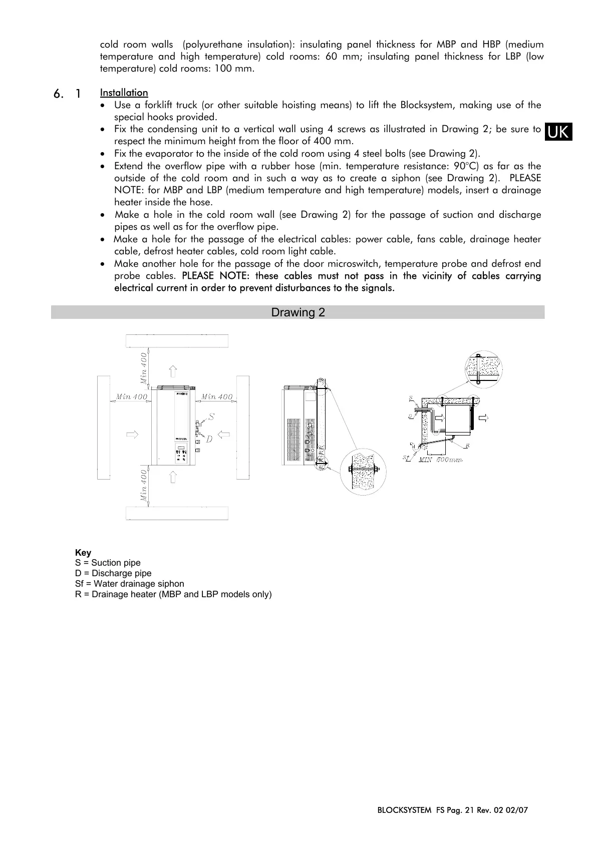
• Fix the condensing unit to a vertical wall using 4 screws as illustrated in Drawing 2; be sure to
respect the minimum height from the floor of 400 mm.
• Fix the evaporator to the inside of the cold room using 4 steel bolts (see Drawing 2).
• Extend the overflow pipe with a rubber hose (min. temperature resistance: 90°C) as far as the
outside of the cold room and in such a way as to create a siphon (see Drawing 2). PLEASE
NOTE: for MBP and LBP (medium temperature and high temperature) models, insert a drainage
heater inside the hose.
• Make a hole in the cold room wall (see Drawing 2) for the passage of suction and discharge
pipes as well as for the overflow pipe.
• Make a hole for the passage of the electrical cables: power cable, fans cable, drainage heater
cable, defrost heater cables, cold room light cable.
• Make another hole for the passage of the door microswitch, temperature probe and defrost end
probe cables.
PLEASE NOTE: these cables must not pass in the vicinity of cables carrying
electrical current in order to prevent disturbances to the signals.
Drawing 2
Key
S = Suction pipe
D = Discharge pipe
Sf = Water drainage siphon
R = Drainage heater (MBP and LBP models only)
off
on
set
 Loading...