RIX Industries MAN-2PS2B-N2 Page 7
4.4 Control logic Description
The following explains the logic sequence as reflected on the electrical schematic (Figure 16 in
Appendix):
1. With power applied to the unit and the HOA selector switch (HOA) in HAND, push
the START pushbutton.
2. The two pressure switches, suction (PSIL) and discharge (PSR) are connected in
series to the motor controller. If the suction pressure is high enough to close the
suction pressure switch, and the discharge switch remains closed (pressure below
the switch "closed" setting) the compressor will start.
3. Current passes through the two closed pressure switches, the closed time delay
relay (TDR), and energizes the starter coil (C-1). The starter coil starts the main
drive motor. The fan motor and hour meter also operate at this point. The green
light (LG) will energize indicating the compressor is running. Tripping of either the
suction or discharge switch will break current to the coil (TDR) which will stop the
drive motor.
4. The compressor may also be run in the automatic mode by selecting AUTO on the
HOA switch. All features are the same as described above except that after the inlet
or discharge switch shut down the unit, the compressor will automatically restart
when the switches are moved to the "closed" setting. The compressor will continue
cycling until the selector switch is moved to either HAND or OFF.
5. The unit may be stopped at any time by switching the HOA to OFF.
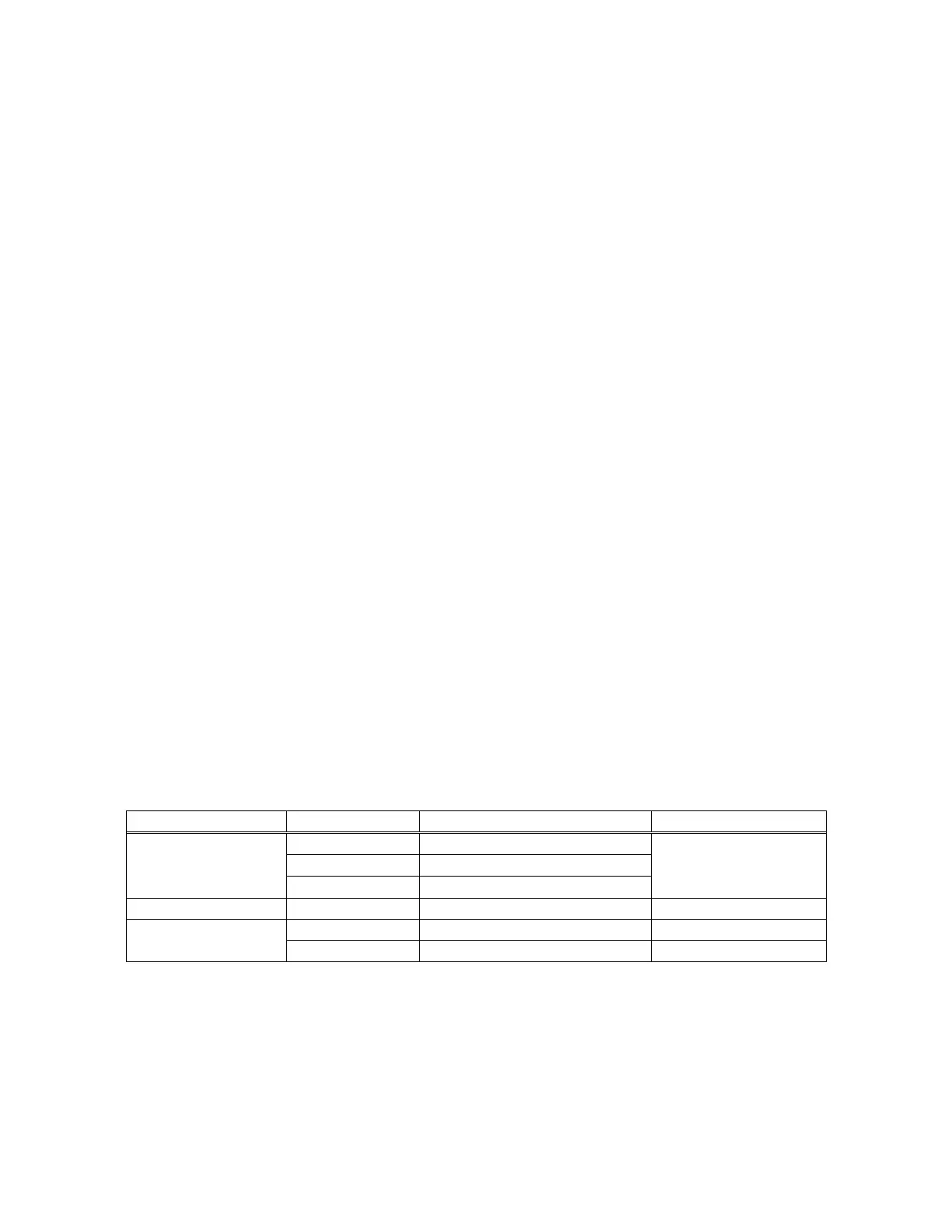
4.5 Safety Device Set Points
The following safety devices have been provided at the set points noted below. Pressure switch
settings may be adjusted to User’s needs but set points shall not exceed the design constraints given
in Compressor Specifications. Do not adjust relief valve settings.
pressure build up