IMR01H01-E4
2
1. OUTLINE
As a multi-point digital controller of a DIN size 96
×
96 mm, there are MA900 of 4-channel type and MA901 of 8-channel type. This
manual describes the specifications, setting, mounting and wiring. For the communication function, see the
Communication Instruction
Manual (IMR01H02-E
#
##
#
)
.
1.1 Checking the Product
When unpacking your new instrument, please confirm that the following products are included. If any of the products are missing,
damaged, or if your manual is incomplete, please contact RKC sales office or the agent.
!
MA900 (MA901): 1
!
Mounting brackets: 2 (Waterproof/dustproof option: 4)
!
Instruction Manual: 1 (IMR01H01-E4)
!
Mounting screws [with hexagon nuts]: 2 (Waterproof/dustproof option: 4)
1.2 Confirmation of the Model Code
Check whether the delivered product is as specified by referring to the following model code list. If the product you received is not the one
ordered, please contact RKC sales office or the agent.
MA900 - 4
$
$$$
-
$
$
-
$
∗
$
$
$
-
$
$
/
$
/ Y
MA901 - 8
$
$$$
-
$
$
-
$
∗
$
$
$
-
$
$
/
$
/ Y
(1) (2) (3) (4) (5) (6) (7) (8) (9) (10)(11) (12)
(1) Number of channel
4: 4 channels (MA900) 8: 8 channels (MA901)
(2) Control action type
F: PID control with autotuning (Reverse action)
D: PID control with autotuning (Direct action)
W: Heat/cool PID control with autotuning (Water cooling)
1
A: Heat/cool PID control with autotuning (Air cooling)
1
(3) Input type/Input range (This code is common to all channels.)
See
%
%%
%
Input Range Table (P. 21)
(4) Output 1 (OUT1 to OUT4)
2
M: Relay contact output 7: Current output (0 to 20 mA DC)
V: Voltage pulse output 8: Current output (4 to 20 mA DC)
T: Triac output
(5) Output 2 (OUT5 to OUT8)
2
N: No output 7: Current output (0 to 20 mA DC)
M: Relay contact output 8: Current output (4 to 20 mA DC)
V: Voltage pulse output T: Triac output
(6) Power supply voltage
3: 24 V AC/DC 4: 100 to 240 V AC
(7)
Alarm 1
3
A: Deviation high alarm J: Process low alarm
B: Deviation low alarm K: Process high alarm
4
C: Deviation high/low alarm L: Process low alarm
4
D: Band alarm M: FAIL alarm
E: Deviation high alarm
4
R: Control loop break alarm
F: Deviation low alarm
4
V: SV high alarm
G: Deviation high/low alarm
4
W: SV low alarm
H: Process high alarm
(8)
Alarm 2 (option)
3
N: No alarm J: Process low alarm
A: Deviation high alarm K: Process high alarm
4
B: Deviation low alarm L: Process low alarm
4
C: Deviation high/low alarm M: FAIL alarm
D: Band alarm P: Heater break alarm (CTL6P)
5, 6
E: Deviation high alarm
4
S: Heater break alarm (CTL12)
5, 6
F: Deviation low alarm
4
V: SV high alarm
G: Deviation high/low alarm
4
W: SV low alarm
H: Process high alarm
(9) Alarm 3 (option)
3
N: No alarm H: Process high alarm
A: Deviation high alarm J: Process low alarm
B: Deviation low alarm K: Process high alarm
4
C: Deviation high/low alarm L: Process low alarm
4
D: Band alarm M: FAIL alarm
E: Deviation high alarm
4
V: SV high alarm
F: Deviation low alarm
4
W: SV low alarm
G: Deviation high/low alarm
4
(10) Contact input (option)
N: No contact input
D: Contact input (RUN/STOP, Memory area transfer)
(11) Communication Interface (option)
N: No communication function
1: RS-232C (RKC communication)
4: RS-422A (RKC communication)
5: RS-485 (RKC communication)
6: RS-485 (Modbus)
7: RS-422A (Modbus)
8: RS-232C (Modbus)
(12) Waterproof/dustproof (option)
N: No waterproof/dustproof
1: Waterproof/dustproof
1
In case of MA901, heat/cool PID action can not be specified.
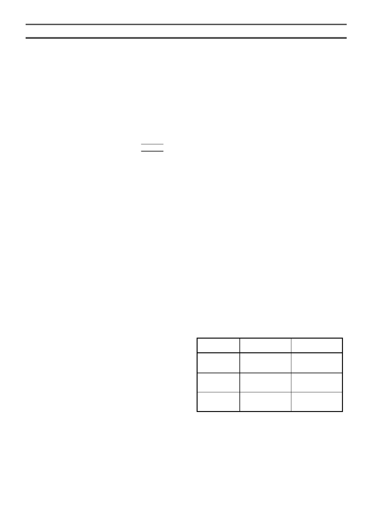
2
Output assignment of output 1 and output 2:
Control
action
Output 1
(OUT1 to OUT4)
Output 2
(OUT5 to OUT8)
F
or
D
action
type
(MA900)
Control output
(CH1 to CH4)
Alarm 3 output
a, b
(CH1 to CH4)
[Option]
F
or
D
action
type
(MA901)
Control output
(CH1 to CH4)
Control output
(CH5 to CH8)
W
or
A
action
type
(MA900)
Heat-side control
output (CH1 to CH4)
Cool-side control
output (CH1 to CH4)
a
When the FAIL alarm is specified, the output 2 is not output.
FAIL alarm is output from the contact output of alarm 3
(terminal No.51 and 52).
b
When the alarm 3 is specified as the output 2, output type is
only relay contact output.
3
The selection of the alarm action type is common to all channels.
4
With hold action
5
For three-phase heater break alarm, special specified code
“Z-168” must be specified at the end of the model code.
Three-phase heater break alarm cannot be specified with
MA901.
6
If the heater break alarm is selected, contact input and
communication function cannot be selected (MA901 only).

 Loading...


