6
IMR01H01-E4
5. SETTING
This chapter describes the operation flowchart of mode and the setting item of each mode. This instrument classes setting item in four
kinds of mode. The mode can be selected by pressing the SET or <R/S key
.
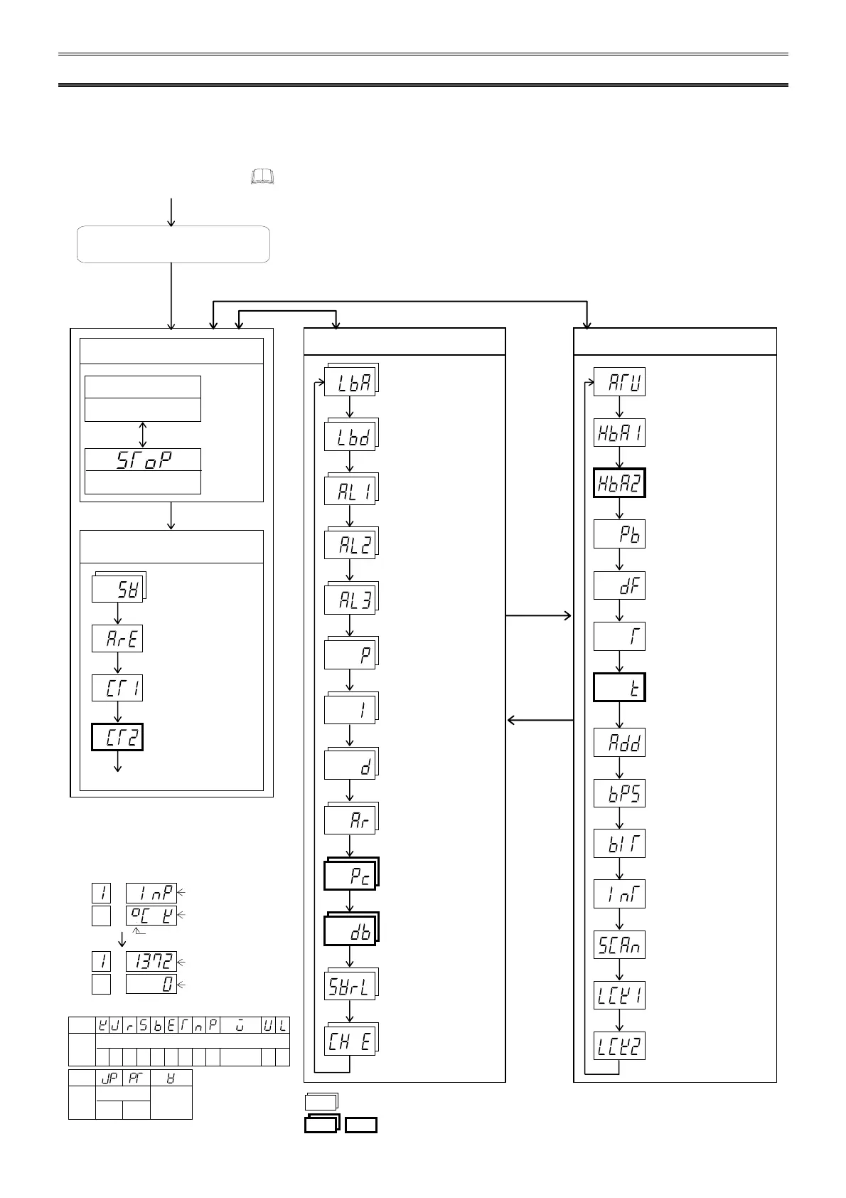
5.1 Operation Flowchart of Mode
*
Input type/Input Range Display
This instrument displays input type code and
input range just after power supply ON by each
2 seconds.
:
Setting item for memory area function
Power ON
Input type/Input range Display
*
•
Regardless of the display time of the input type or input range, control starts about 4 seconds
after the power is turned on.
•
If the key is not pressed for more than one minute, the display will automatically return to the
PV/SV monitor mode.
•
If the function is not selected for all of the channels, that parameter symbol is not displayed.
•
In case of MA901, parameter symbols of the following are not displayed;
Current transformer 2 monitor, cool-side proportional band, overlap/deadband,
heater break alarm 2, cool-side proportioning cycle time
Parameter Setting Mode (P. 10)
Control loop break
alarm
Control loop break
alarm deadband
Alarm 1
Alarm 2
Alarm 3
Proportional band
Integral time
Derivative time
Anti-reset windup
Cool-side proportional
band
Overlap/deadband
Setting changing rate
limiter
Used/unused of
channels
SET key
SET key
SET key
SET key
SET key
SET key
SET key
SET key
SET key
SET key
SET key
SET key
SET key
LbA
Lbd
AL1
AL2
AL3
P
I
d
Ar
Pc
db
SVrL
CH E
SV Setting & CT Monitor Mode
(P. 7)
To PV/SV monitor mode
SET key
S
et value (SV) setting
Memory area transfer
Current transformer 1
monitor
Current transformer 2
monitor
SET key
SET key
SET key
SV
ArE
CT1
CT2
Press the
<
R/S key
while
pressing
the SET
key.
Press the
SET key for
2 seconds.
Setup Setting Mode (P. 8)
Autotuning (AT)
Heater break alarm 1
*
Heater break alarm 2
*
PV bias
*
Digital filter
*
Proportioning cycle
time
*
Cool-side proportioning
cycle time
*
Device address
Communication speed
Data bit configuration
Interval time
Scan interval time
Lock level 1
Lock level 2
SET key
SET key
SET key
SET key
SET key
SET key
SET key
SET key
SET key
SET key
SET key
SET key
SET key
SET key
ATU
HbA1
HbA2
Pb
dF
T
t
Add
bPS
bIT
InT
SCAn
LCK1
LCK2
*
Set the parameter for each channel.
: These items are not displayed with MA901.
Diplay changes
automatically
Press the SET key for 2 seconds.
Press the
<
R/S key while pressing
the SET key.
Press the SET key
PV/SV Monitor Mode (P. 7)
RUN state
Measured value (PV)
Set value (SV)
STOP state
Set value (SV)
Press the <R/S key for
1 second.
Symbo
l
Input type symbol (SeeTable)
Engineering unit (Voltage input: No display)
PVCH
AREA SV
Input range low
Input range high
PVCH
AREA SV
Input Type Symbol Table
Input
Type
Symbol
Thermocouple
W5Re/
W26Re
K J R SBE TN
U L
II
PL
RTD
JPt
100
Pt
100
Symbol
Input
Type
Voltage

 Loading...


