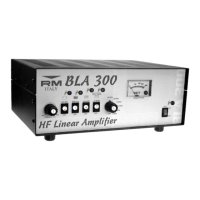
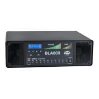
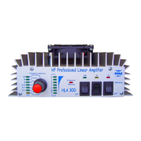
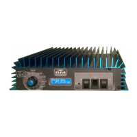
Front / Rear Panel Description
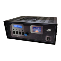
Front Panel
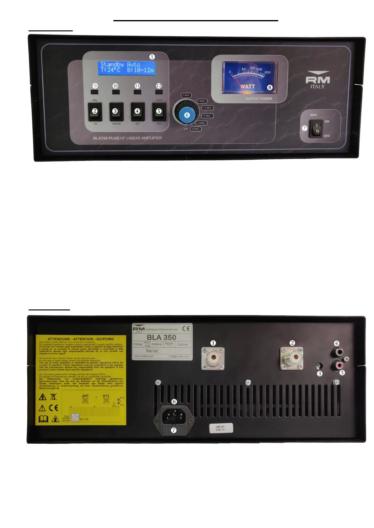
1. LCD Display - displays amplifiers operating parameters and menu system
2. Standby / On - In standby the amplifier does not amplify the incoming signal. Menu adjustments can
be made in this mode
3. OK /SSB - Menu setting conformation and SSB RTX delay ’on’ / ’OFF’, if the amplifier is used in
VOX mode
4. SET - Menu Switch
5. AUT / MAN - Auto or manual band filter mode
6. BAND - Manual band filter selector
7. MAIN - primary AC ’ON’ / ‘OFF’ switch
8. Output Power Meter
9. ON - Amplifier active LED
10. TX - Amplifier in Transmission LED
11. Warning - Alarm LED. Illuminates when there is an alarm condition, excessive temperature / antenna
SWR etc.
12. MAN - When manual filter selection is selected this LED will illuminate
Rear Panel
1. ANT - SO239 Antenna Output connector
2. RTX - SO239 Transceiver input connector
3. ALC - ALC output level adjustment
4. ALC - ALC output connector RCA / Phono socket
5. PTT - PTT Input Connector RCA / Phone socket (Active Low)
6. IEC European AC input socket
7. AC Fuse receptacle (2x4A (230Vac) 5x20mm, Fast, glass fuses)
3


 To Next Page