IMPORTANT NOTICE!
Safety Definitions
These instructions contain information that is very important to know and understand. This information is pro-
vided for safety and to prevent equipment problems. To help recognize this information, observe the following
symbols:
WARNING indicates a potentially hazardous situ-
ation which, if not avoided, could result in property
damage, serious personal injury, or even death.
CAUTION indicates a potentially hazardous situ-
ation which, if not avoided, may result in property
damage, or minor or moderate personal injury.
CAUTION
CAUTION used without the safety alert symbol
indicates a potentially hazardous situation which,
if not avoided, may result in property damage.
NOTE
Refers to important information and is placed in italic
type. It is recommended that you take special notice
of these items.
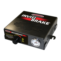
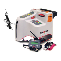
InvisiBrake specifications
Controller height ..........................................2¾ inches
Controller width ...........................................8¾ inches
Controller length ..........................................8¾ inches
Voltage .......................................................12 volts DC
Fuse size ......................................................... 20 amp
Operating temperature range
............................... -2° to
+
150° F (-19° to
+
66° C)
Maximum amperage draw ...........................10.8 amps
Idle amperage draw ............................................. 6 mA
Battery recharging rate ...........................up to 2 amps
Approximate maximum air pressure .................. 80 psi
Required tools
• drill with ½" and 5/16" bits (The ½" bit is only
necessary if there is no pre-existing hole through
the firewall; the 5/16" bit is necessary if you will
drill a hole through the motorhome dashboard for
the LED monitor light)
• test light
• multi-meter
• wire strippers or crimpers
• 7/16", 1/2" and 9/16" wrenches
• 5/32" Allen wrench
• adjustable wrench
• 5/16" and 3/8" drivers
Read all instructions before install-
ing or operating InvisiBrake. Failure
to understand how to install or oper-
ate InvisiBrake could result in prop-
erty damage, personal injury or even
death.
Table of contents
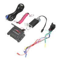
Components .............................................................. 1
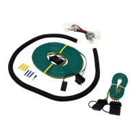
Towed vehicle wiring diagram ................................... 2
Verify the application ................................................. 3
General warnings and cautions ................................. 4
Installation instructions ......................................... 5-17
Plan the installation ............................................ 5-8
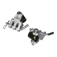
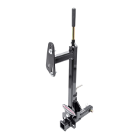
Begin the installation —
Attach the clamp, pulley and bracket ........... 9-10
Adjust the cable .................................................. 10
Route the cable housing
and attach the air line ..................................... 10
Attach the vacuum line .........................................11
Check the existing lighting .................................. 12
Install the break away system;
attach the power and ground wires ................ 12
Attach the four-wire flat harness;
attach the controller ....................................13-14
Install the monitor system ...............................14-15
Test the system ...............................................16 -17
If you are a professional installer…
…return these instructions to the owner, for the
owner's future reference.
All illustrations and specifications contained herein are based on
the latest information available at the time of publication. ROADMAS-
TER, Inc. reserves the right to make changes, at any time, without
notice, in material, specifications and models, or to discontinue
models.