robert juliat Route de Beaumont F 60530 Fresnoy-en-Thelle phone: 33 (0)3.44.26.51.89 - fax: 33 (0)3.44.26.90.79 - www.robertjuliat.fr
Robert Juliat reserve the right to change or alter any of the items detailed on this page, to increase or improve manufacturing techniques without prior notice.
VALID SINCE : 09.05.01
DocTech1039_1439_090501.ind
14
TECHNICAL FILE
2500W HMI FOLLOW SPOT
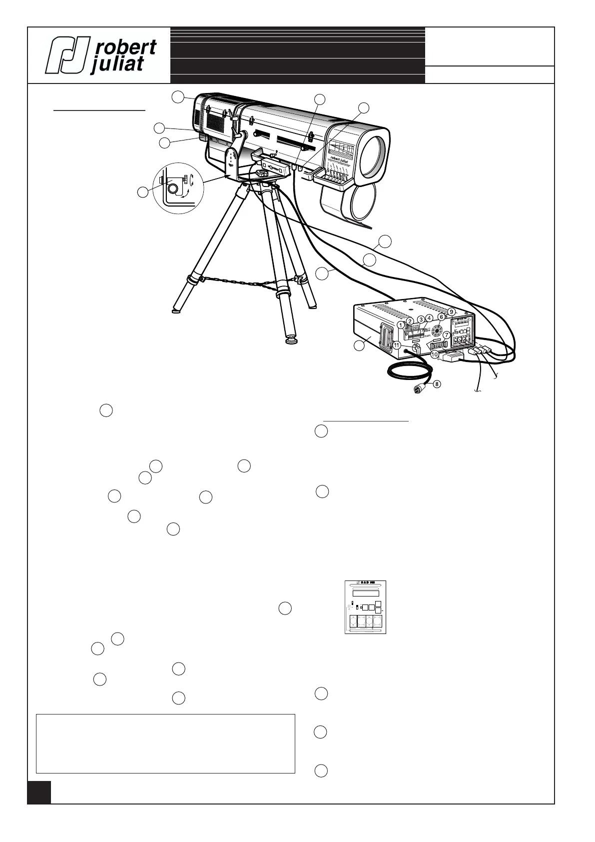
CONNECTIONS.
1039B & 1439B
Lighting unit / Power supply connection.
- Connect the lamp cable C to the connector 7 of the
ballast and connector e to the lighting unit.
- Lock the cable C into the cable lock j .
- Connect the cable D to the connector ( d ) of the
ballast and to the connector g of the lighting unit "XLR7".
- Place the lamp into position - refer to page 16.
- Connect the DATA line on connector ( a ) "XLR5" or
the analog command to the the connector ( c ) "XLR4".
( For the connection congurations : refer to page 24 ).
- Connect the optional units that are possible, to connector h
( Only DATA ).
- Plug the cable 8 to the mains. If the power is present, the
checklight 1 lights up immediately.
- Engage the automatic breaker 3 and check that the CAD 900
protection 4 is well engaged.
- Engage the automatic breaker 2 .
WARNING !
- Never open the lantern's bonnet when the lighting unit is on.
- Do not change the safety switches.
- Never connect to a dimmable channel.
- Use only when lamp is in place.
A 1039 B/1439 B - Motorized shutter with CAD.
e - EM HARTING 16 x 16A power socket.
f - 10A. 250V. EEC - Female mains socket.
g - EM XLR7 shutter + DATA.
h - EF XLR5 output DATA.
B Power supply unit.
1 - Mains checklight.
2 - UNI + N 2A-C automatic breaker.
3 - General 25A automatic breaker.
4 - UNI + N 2A-C automatic breaker.
6 - Ventilation opening
(DON'T OBSTRUCT THE AIR GAPS).
7 - EF HARTING 16 x 16A - 2 latch connector.
8 - Mains cable 3 x 4 mm
2
(3m)+P17 32A. + T plug.
9 - CAD 900 local controls.
10 - Rating plate.
11 - Power supply selector :
208V. 60Hz, 230V. 50Hz & 245V. 50Hz.
Position locked by a screw.
C Lamp cable.
Cable H07 RN-F 19G1,5 mm
2
length 3m tted
with 16 x 16A M/F HARTING connectors.
D Shutter cable.
14 conductors reinforced shielded cable - length 3m
tted with XLR7 M/F connector.
E Analog control fader cable.
14 conductors reinforced shielded cable - length 3m
tted with XLR4 M/F connector.
DATA
DMX 512 Line.
DATA Line.
DESCRIPTION.
ERROR
DATA
EXT. DIGI.
EXT.
LOCAL
LOCK
SELECT EXIT
+
CONTROL SHUTTER
DATA
0/10V
0/10V - DMX 512 - AVAB
C A D 900
RESET
a
b
c d
a - EM XLR5 : DATA input.
b - EF XLR5 : DATA output.
c - EM XLR4 : 0/+10V. input.
d - EF XLR7 : lighting unit output.
B
A
W
A
R
N
I
N
G
:
D
O
N
O
T
T
R
A
N
S
P
O
R
T
T
H
I
S
L
A
N
T
E
R
N
W
I
T
H
L
A
M
P
I
N
S
I
D
E
.
A
T
T
E
N
T
I
O
N
:
N
E
P
A
S
T
R
A
N
S
P
O
R
T
E
R
L
E
P
R
O
J
E
C
T
E
U
R
A
V
E
C
L
A
L
A
M
P
E
M
O
N
T
E
E
.
2
2
0
V
.
2
A
.
C
O
L
O
R
C
H
A
N
G
E
R
S
O
C
K
E
T
L
O
C
K
I
N
G
S
E
R
R
A
G
E
D
O
U
I
L
L
E
e
f
h
g
C
D
E
Power supply unit
(P.S.U.)
j
Mains voltage.
- Check the conformity of the power supply unit.
Rating plate 10 : Lamp power.