6-3
TIMING ADJUSTMENT
(See
Figs.
47,48
and
49)
The spark is timed to occur at
23”
before the piston reaches
TDC
on the compression stroke.
This
spark advance of
23”
is
controlled by the breaker point opening and tius advance is obtained when the breaker point opening is adjusted according
to
the
BREAKER
POINT ADJUSTMENT
to its proper point gpening. However, the advance timing is more accurately ad-
justed through the following procedures using a timing tester as
shown
in Fig.
48.
NOTE: Refer
to
section
“4-1’1
IGNITION”
and
“13.
CHECKS
and
CORRECTIONS.”
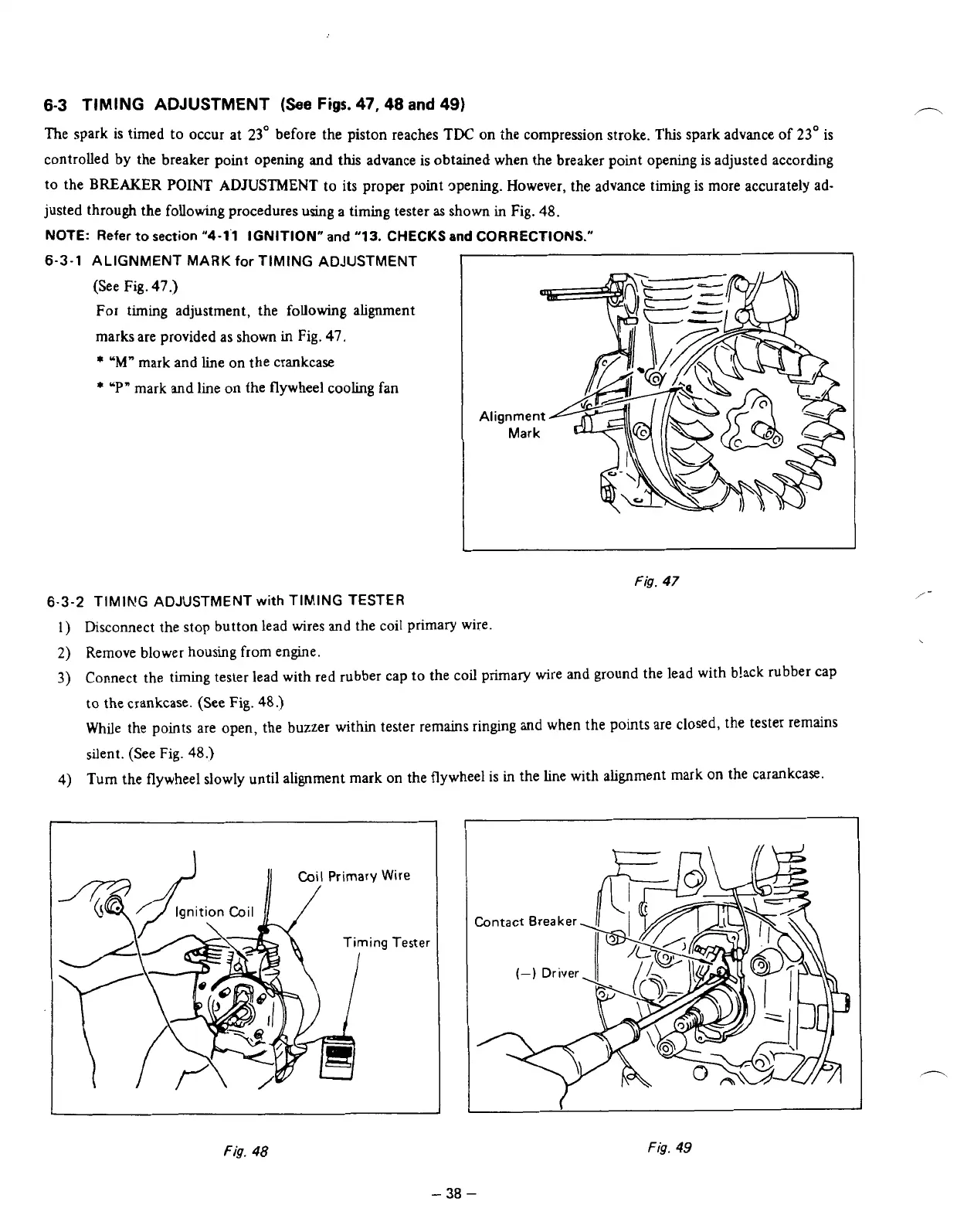
6-3-1
ALIGNMENT
MARK
for TIMING ADJUSTMENT
1
(See Fig.
47.)
For timing adjustment, the
following
alignment
marks are provided as shown
in
Fig.
47.
*
‘M”
mark and line on the crankcase
*
‘P-
mark and line on fhe flywheel cooling fan
Fig.
47
6-3-2
TIMING ADJUSTMENT
with
TIMING TESTER
1)
Bsconnect the stop button lead wires
and
the coil primary wire.
2)
Remove blower housing
from
engine.
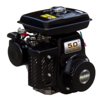
3)
Connect the timing tester lead with red rubber cap
to
the coil primary wire and ground the lead with b!ack rubber cap
to
the crankcase. (See Fig.
48.)
While the points are open, the buzzer within tester remains ringing and when the
points
are closed, the tester remains
silent. (See Fig.
48.)
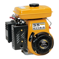
4)
Turn
the flywheel slowly until alignment mark on the flywheel is in the line
with
alignment mark on the carankcase.
Fig.
48
/-
Fig.
49
-
38
-