Red
Red
White
White
0.57 kΩ
0.57 kΩーーー
ーーー
2P Connector for AC output
a
a
b
c
b
2.5 MΩ
〜
ーーー 5 MΩ〜
2.5 MΩ
〜 10 MΩ〜 10 MΩ〜
c
4 MΩ〜
10 MΩ〜ーーー
ーーー
ーーー
Stator wire Terminal
Apply red needle of the circuit tester
d
4 MΩ〜
10 MΩ〜
d
2.5 MΩ
〜 10 MΩ〜 10 MΩ〜
Apply black needle
of the circuit tester
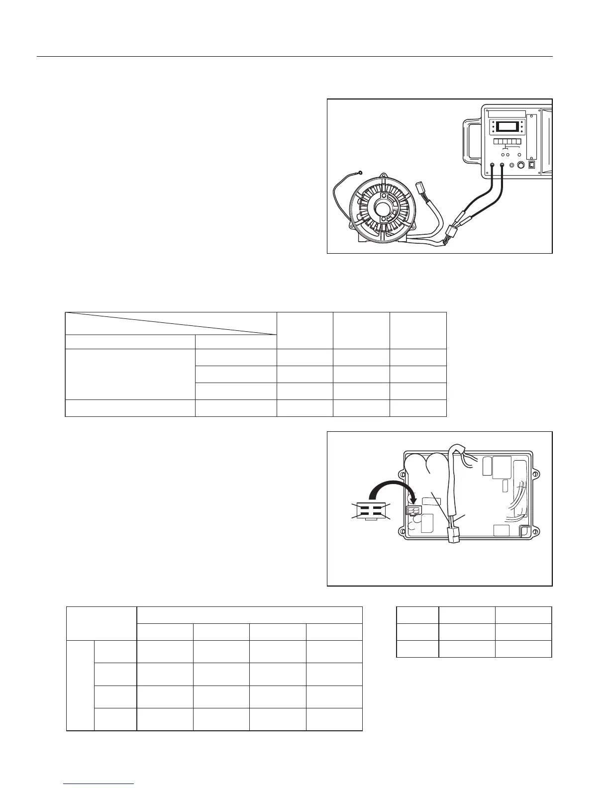
(2)INVERTER UNIT
Check if there is no color change or blister on the
filling resin, and confirm that there is no damage or
color change in the electrical parts, electrical wires,
or the connectors.
And, check the resistance at the 2P connector for
AC output and at the 4P connecter for the stator
wire terminals.
White
Red
a
b
c
d
2P connector
for AC output
Stator wire
terminal
4-4) CHECKING FUNCTIONAL MEMBERS
(1)STATOR
Measure the winding wire resistance. Check the
resistance of the wires that comes out from the
stator using a tester, referring to the following table.
NOTE: When measuring according the numerical value
shown in the chart, tolerance should be
considered because the inaccuracy of the tester.
If an accurate value is needed, measure by
electric resistance using an Ohm-meter.
While doing this, use caution to avoid contact
resistance.
AC 240V
Specification
Color of the wires
4.2Red-Blue
Unit;Ω
Generator wire resistance
4.2Blue-White
4P Connector (AC output line)
4.2White-Red
2.1Yellow-Yellow/Blue
Diode Rectifier Connector
AC 230V
Specification
4.2
4.2
4.2
2.1
AC 120V
Specification
1.2
1.2
1.2
0.2

 Loading...