EasyManua.ls Logo

Rockford Fosgate PM100X1 User Manual

Rockford Fosgate PM100X1
2 pages
To Next Page IconTo Next Page
Page #1 background imageLoading...
Page #1 background image
Amplifier Quick Setup
Wire Harness Color Code
Amplier
Source Unit
White Input (-)
Yellow Input (+)
Black Ground
Blue Speaker Out (+)
Green Speaker Out (-)
WHITE = INPUT (-)
BLACK = GROUND
YELLOW = INPUT (+)
GREEN = SPKR OUT (-)
BLUE = SPKR OUT (+)
INPUT (-)
GROUND
INPUT (+)
OUTPUT (-)
OUTPUT (+)
LEFT OUTPUT (+)
LEFT OUTPUT (-)
LEFT SPEAKER RIGHT SPEAKER
RIGHT OUTPUT (+)
RIGHT OUTPUT (-)
INPUT (-)
GROUND
INPUT (+)
OUTPUT (-)
OUTPUT (+)
* Specifications subject to change without notice. Images depict typical setup.
Refer to manual for additional wiring options.
Connect to chassis
ground of vehicle
*Keep grounds as short as possible
Question and Answer IconNeed help?

Do you have a question about the Rockford Fosgate PM100X1 and is the answer not in the manual?
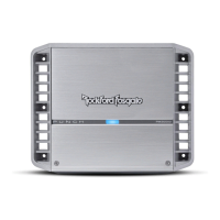
Rockford Fosgate PM100X1 Specifications

General IconGeneral
BrandRockford Fosgate
ModelPM100X1
CategoryAmplifier
LanguageEnglish

Summary

Amplifier System Wiring Overview

Source Unit and Speaker Connections

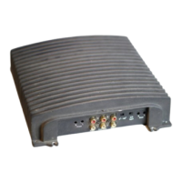
Details the wiring from the source unit outputs to amplifier inputs and amplifier outputs to speakers.

Wire Harness Color Identification

Explains the color coding for amplifier wire harness connections.

Amplifier PM100X1 Features and Operation

LED Power and Protect Indicators

Explains the blue Power LED and red Protect LED status and their meanings.

Crossover Frequency Selection

Details the selectable 12dB/Oct HP Butterworth Crossover settings (60, 80, 100 Hz).

Input Impedance Configuration

Describes the switch for selecting 2 or 4 ohm input impedance capability for the source unit.

IP67 Water Resistance Features

Emphasizes installing rubber switch covers for water and dirt protection of the amplifier.

Related product manuals