12 Logic Module, Internal CompactFlash, and RAM
Publication 2711P-IN004J-EN-P - September 2009
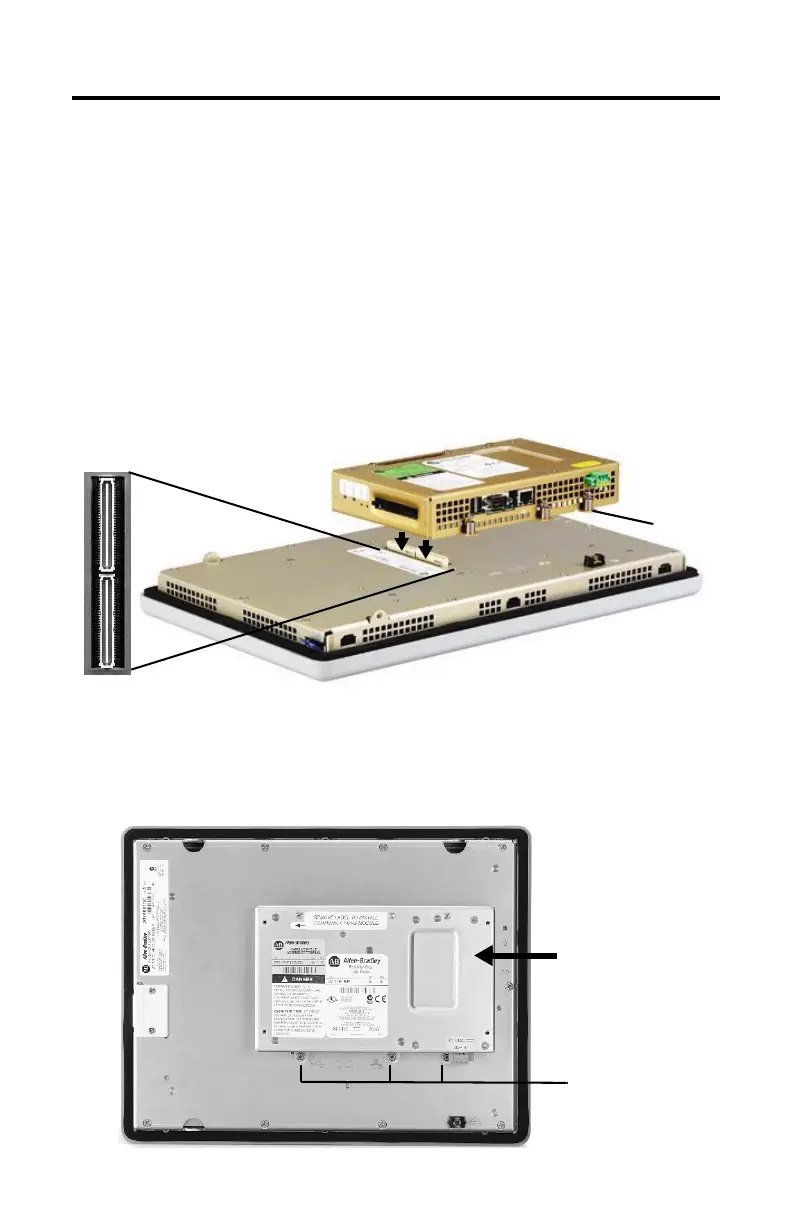
Install a Logic Module
If the display module and logic module are ordered as separate components, attach the logic
module to the display module before panel installation.
1. Disconnect power from the terminal.
2. Set the display module of the terminal display-side down on a clean, flat, stable
surface to avoid scratches.
3. Position the logic module over the back of the display module until the two
connectors on the bottom of the logic module align with the connectors on the
display module.
4. Push down on the logic module until firmly seated.
5. Tighten the six captive screws that secure the logic module to the display module to a
torque of 0.58 N•m (5…7 lb•in).
Captive
Screw
Logic Module
Captive Screws
on Top and Bottom

 Loading...


