34 Rockwell Automation Publication 440R-UM013F-EN-P - July 2021
Chapter 4 Configuration
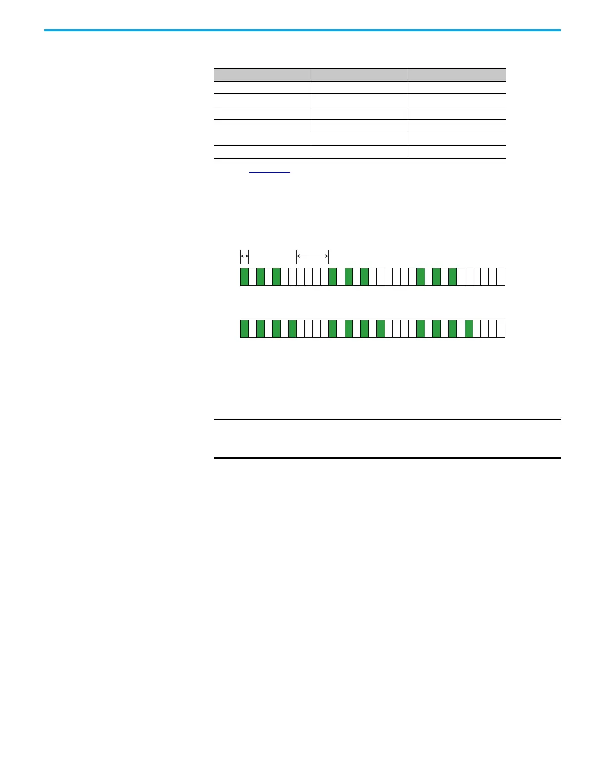
Figure 27 shows an example of the blinking patterns for the EMD
expansion safety relay. The indicators flash for 0.5 seconds to indicate
the switch settings. The number of flashes is equal to the switch
setting. The blinking pattern repeats after a 2 second pause.
Figure 27 - EMD Expansion Safety Relay Status Indicators Flashing in Configuration Mode
5. Cycle the power to store the settings.
After power-up, the current switch settings are compared to the values
in the EEPROM (makes sure that the switches were not changed while
power was off), and the input and output circuits are checked. Upon
successful completion of the internal checks, the relays are ready for
operation.
Table 8 - Configuration Confirmation
Safety Relay Status Indicator Switch Setting
CI IN Reset
DI IN 1 Logic
DIS IN 1 Logic
EMD
B1 Range
Logic IN Time
SI IN Reset
IMPORTANT To keep your GSR safety relay from permanently faulting, complete the
configuration process by cycling the relay power within 5 minutes of
rotary switch configuration.
B1 - Indicates that the RANGE Switch is set to 3.
Logic IN - Indicates that the TIME Switch is set to 4
2 s
Pause
0.5 s
Flash
 Loading...


