Rockwell Automation Publication 440R-UM013F-EN-P - July 2021 49
Chapter 9 Application and Wiring Examples
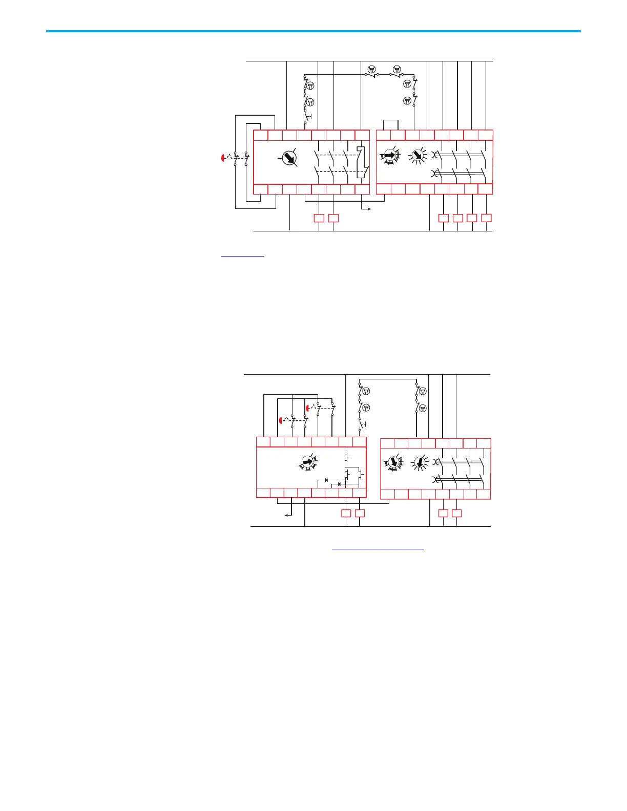
Figure 49 - EMD Safety Relay - Off Delay
Figure 50 shows the EMD safety relay that is configured for a 2.1 second
on-delay. The single wire safety signal from terminals L11 to L12 instructs the
EMD safety relay to turn on and off. When the reset button is pressed, the DIS
safety relay outputs turn on immediately. After a 2.1 second delay, the EMD
safety relay outputs turn on.
The DIS safety relay monitors contactors K1…K4 and the status of the EMD
safety relay by sourcing the reset signal from the X32 terminal on the EMD
safety relay.
Figure 50 - EMD Safety Relay - On Delay
The EMD safety relay in Figure 51 on page 50 is configured for a maximum of a
100 second jog. The single wire safety signal from terminals L11 to L12 enables
the EMD safety relay. When enabled, the jog switch can be pressed and held
closed to turn on the EMD safety relay outputs. If the jog button is released
before the 100 second time, the EMD safety relay outputs turn off. If the jog
button is held longer than 100 seconds, the EMD safety relay outputs only turn
on for 100 seconds.
A1
L11
X32B1 B2
L12 18 38 4828
17 37 4727
A2
EMD
440R-EM4R2D
0
1
2
3
4
5
6
7
8
9
1
2
3
4
5
67
8
10
9
K1
24V DC
24V Com
K2
K6
K5
K3
K4
K1
K2 K3 K4
K5 K6
S11
S12
S21
S22
S34A1 13
L11A2 14
23
24
33 41
34 42
CI
440R-S13R2
0
MM
AM
RESET
Reset
To PLC
RANGE
TIME
0
1
2
3
4
56
7
8
DIS
440R-D22S2
S32 A1
Y32
S21S11 S22S12 S34
S42
L12 L11
34A2 44
14 24
K1
24V DC
24V Com
K2
K3
K4
K1
K2
A1
L11
X32B1 B2
L12 18 38 4828
17 37 4727
A2
EMD
440R-EM4R2D
0
1
2
3
4
5
6
7
8
9
1
2
3
4
5
67
8
10
9
K3 K4
LOGIC
Reset
To PLC
RANGE
TIME
 Loading...


