10 Rockwell Automation Publication 1719-IN001D-EN-E - November 2020
1719 Ex I/O Installation Instructions
Installing the Separation Plate
IEC 60079-14 and IEC 60079-11 require that a thread dimension of at least 50 mm must always be maintained between intrinsically safe and non-intrinsically safe circuits.
When using the 1719-A8 chassis, the distance between the terminals of the I/O module in the first slot and the RJ45 connector on the 1719-AENTR adapter is not large enough.
Install a separation plate (1719-SP1) between the adapter and the first I/O module slot to help ensure that intrinsically safe and non-intrinsically safe circuits meet the
minimum distance.
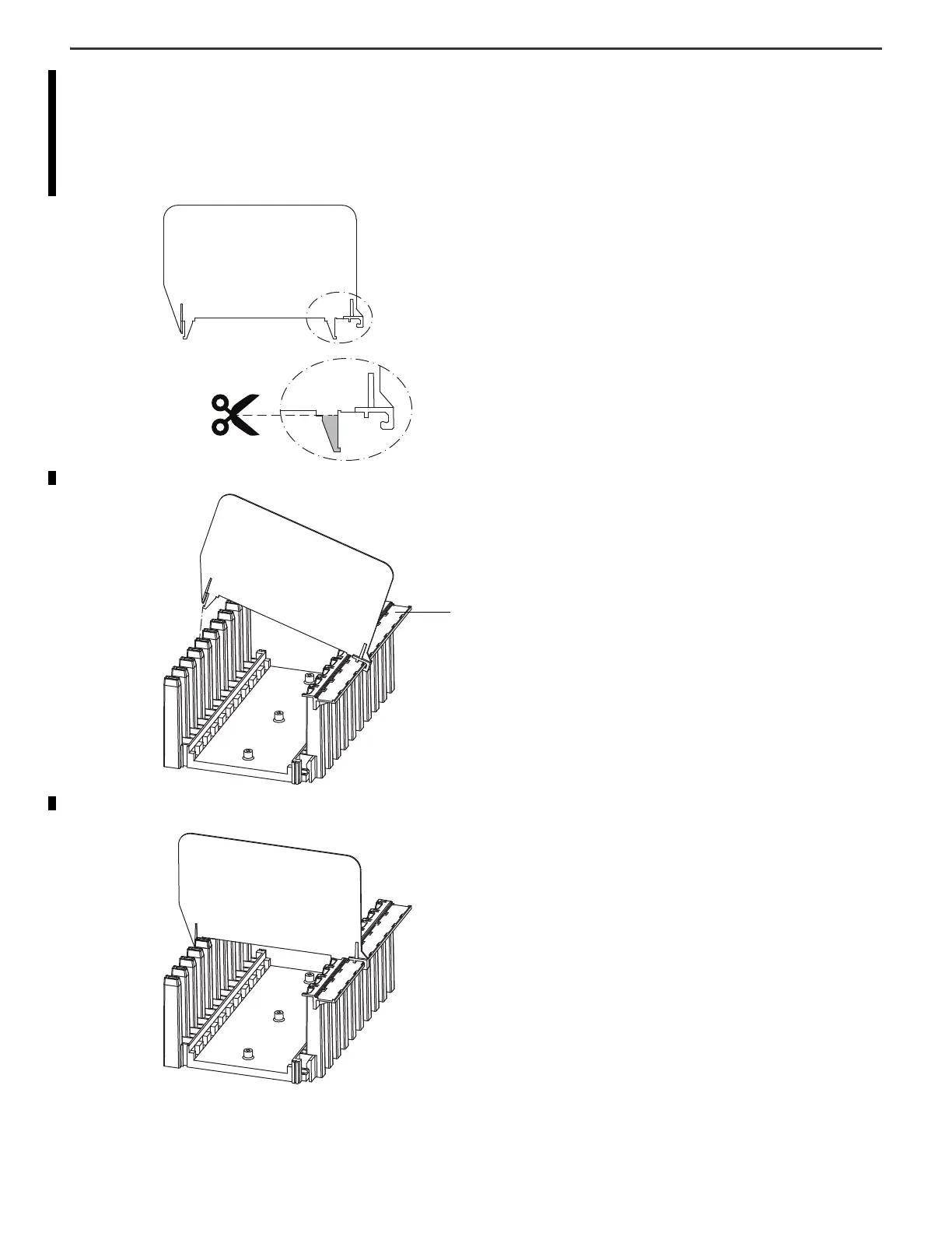
1. Use a wire cutter to remove the pin that is located near the catch on the separation plate.
2. Hook the catch onto the label carrier at the top of the chassis.
3. Insert the pin into the plastic holder at the bottom of the chassis.
The pin snaps into place
Label carrier
Top of chassisBottom of chassis

 Loading...

