Rockwell Automation Publication 1719-IN001D-EN-E - November 2020 13
1719 Ex I/O Installation Instructions
Pt100 Short Circuit
1. Short circuit the Pt100 sensor.
2. Monitor the tag for the I/O module and make a note of the measured value.
3. In the Add-on Profile, using the Ch0x dialog, set the measuring input of the I/O module to 2-wire measurement with a Pt100 sensor.
4. Enter the measured resistance in the Wire Resistance field. The maximum permissible wire resistance is 50 Ω.
For more information, see the Add-on Profile help topic for the 1719-IR4B module.
Use a Calibrating Resistor
1. Use a calibrating terminal with an integrated calibrating resistor in the sensor supply line.
2. In the Add-on Profile, using the Ch0x dialog, set the measuring input of the I/O module to 2-wire measurement with a Pt100 sensor.
3. In the Add-on Profile, set the wire resistance to 20 Ω.
4. Replace the Pt100 sensor at the measuring point with a 100-Ω measurement resistor.
5. To measure the resistance, monitor the tag for the I/O module.
6. Set the displayed value to 0 C using the calibration potentiometer.
7. Then reconnect the Pt100 sensor.
For more information, see the Add-on Profile help topic for the 1719-IR4B module.
EtherNet/IP Connection
Cable Lengths
The following table relates to standard applications.
Network switches or fiber-optic cables can be used to extend the cable length.
Potential Equalization and Shielding
Interference
Electromagnetic fields can interfere with the communication path.
WARNING: Risk of explosion
• Observe the wiring specifications set out in IEC 60079-14 or NEC 500-510 for wiring in Zone 2 or Division 2. Only connect or disconnect EtherNet/IP™ and
power cables when the area is safe.
• Accessories that do not meet the requirements for use in hazardous areas can cause explosive mixtures to ignite.
• Only use accessories and devices that are approved for use in the respective environment.
Bus system Transfer rate Max cable length
EtherNet/IP 10/100 Mbps 100 m (328 ft)
IMPORTANT
The following sections cannot provide the reader with a complete picture of all requirements in terms of grounding, shielding, and lightning
protection. More information on this topic can be found in the technical literature and the applicable standards.
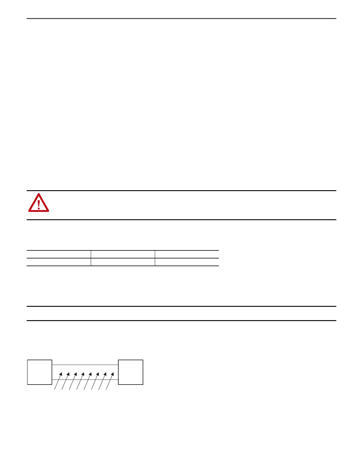
Interfering signals caused by induction in parallel conductors

 Loading...

