6 Rockwell Automation Publication 1719-IN001D-EN-E - November 2020
1719 Ex I/O Installation Instructions
Installing the Backplane
1. Install the backplane horizontally on the DIN rail (Allen-Bradley® part number 199-DR1; 46277-3; EN50022).
2. If you install the backplane vertically, position the power supplies at the top to achieve a favorable heat distribution. Make sure that the maximum ambient
temperature for the components is not exceeded.
For more information, see Appendix B - Technical Data of the 1719 Ex I/O User Manual, publication 1719-UM001
.
Connections
1719-A8 Connections
S1 Switch Positions and X03 Terminal Assignment (1719-A8)
The S1 switch and X03 terminal control the output deactivation of the I/O modules.
The output deactivation of the I/O modules only works for I/O modules that are equipped with a deactivation feature (1719-OB2, 1719-OB2L). I/O modules with and without a
deactivation feature can be installed on the same backplane; however, only the I/O modules that are equipped with a deactivation feature are controlled by the output
deactivation.
If I/O modules that are equipped with a deactivation feature are installed on the backplane, these modules can be deactivated using an external switch
.
ATTENTION: This product is grounded through the DIN rail to chassis ground. Use zinc-plated yellow-chromate steel DIN rail to assure proper
grounding. The use of other DIN rail materials (for example, aluminum or plastic) that can corrode, oxidize, or are poor conductors, can result in
improper or intermittent grounding. Secure DIN rail to mounting surface approximately every 200 mm (7.8 in.) and use end-anchors appropriately.
ATTENTION: Damage to equipment
Equipment can be damaged by voltages that are too high, for example, in temporary faulty operation.
Ensure that the supply voltage of the power supplies used in Zone 2 does not exceed 33.6V DC (24V x 1.4).
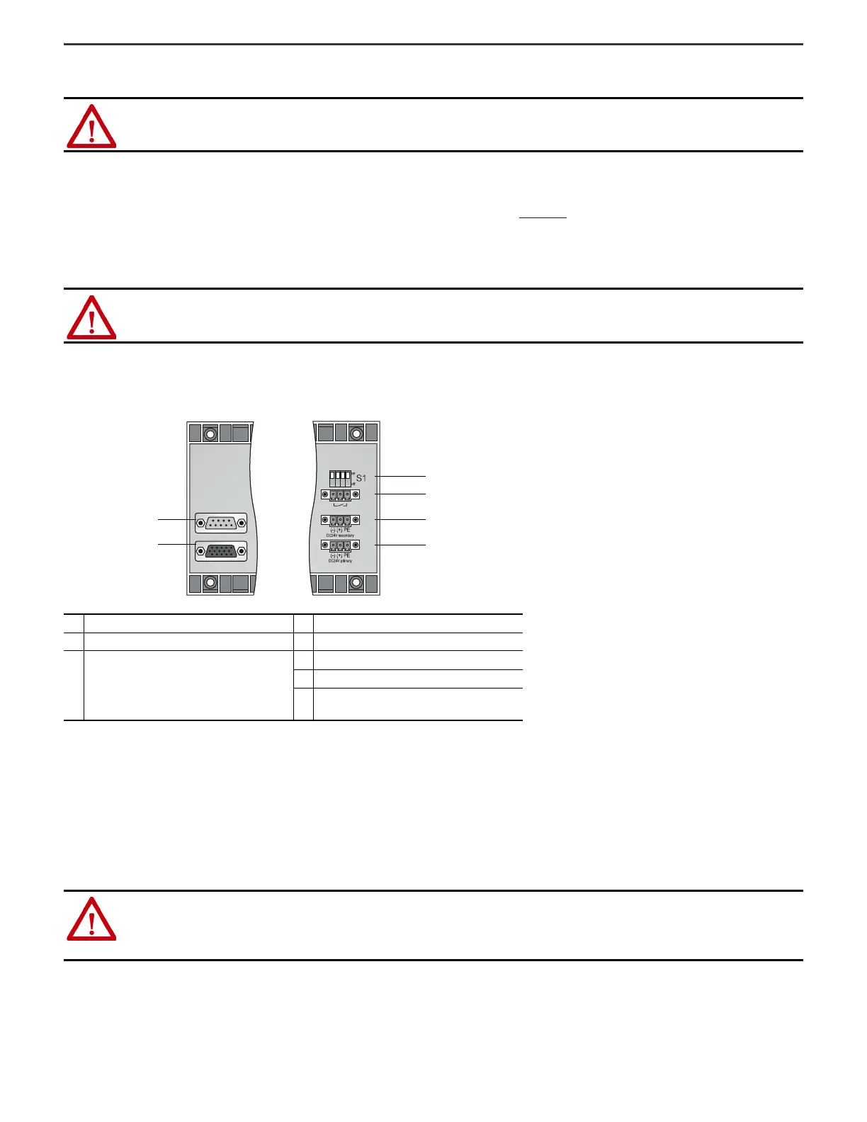
Description Description
1 X6: Service interface. Currently not used. 3 S1: Function switch
2
X7: Extension connection for 1719-A24
extension chassis.
Note: Online addition of an extension
backplane while the system is in Run mode is
not supported.
4 X03: Output deactivation of the I/O modules
5 X02: 24V DC redundant power supply
6 X01: 24V DC power supply
ATTENTION: Damage to equipment
• Do not handle connections improperly as this can damage the backplane.
• Never supply a control voltage to X03.1…X03.3. On backplanes 1719-A8, output deactivation of the I/O modules can be controlled by a voltage-free
contact only.
• Only operate multiple adjacent backplanes using a common contact to avoid equalizing currents.
1
2
3
4
5
6
Left side Right side

 Loading...

