Rockwell Automation Publication 1719-IN001D-EN-E - November 2020 7
1719 Ex I/O Installation Instructions
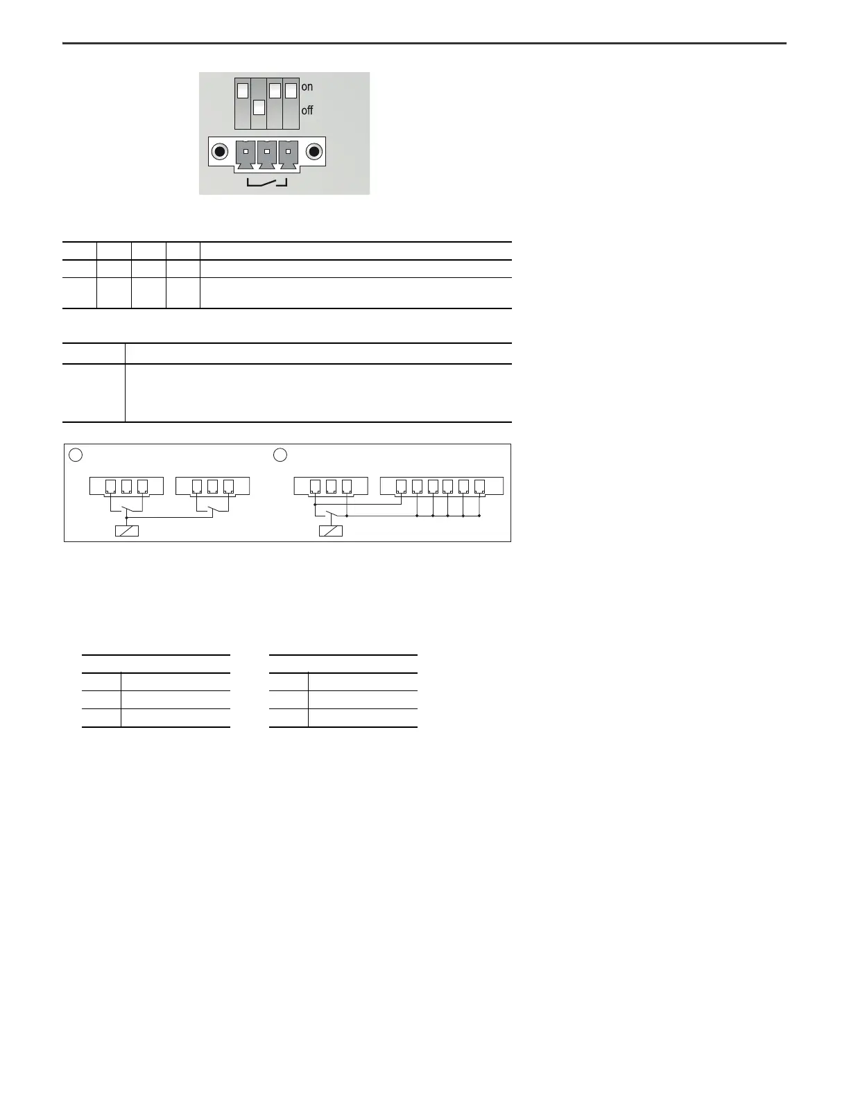
Connector X03
1 = Control for two base backplanes
2 = Base and extension backplane, which is controlled in common
X02 and X01 Terminal Assignment (1719-A8)
S1 Function Switch Positions (1719-A8)
S1.1 S1.2 S1.3 S1.4 Effect
ON ON ON ON Deactivation of the I/O modules is disabled.
ON OFF
ON/
OFF
ON/
OFF
Deactivation of the I/O modules that are equipped with a deactivation
feature is controlled by a voltage-free contact at X03.
X03 Terminal Assignment (1719-A8)
Terminal Description
X03.1…X03.x
For external, voltage-free contact, galvanically isolated from other contacts and
potentials, see Connector X03 item 1 on the figure below.
When interconnecting two base backplanes, see item 1. When interconnecting a base
backplane and an extension backplane, see item 2.
1 2
XX XX
03.603.503.403.1 03.2 03.303.1 03.2 03.303.1 03.2 03.303.1 03.2 03.3
1719-A8 1719-A81719-A8 1719-A24
X02 Terminal Assignment
X02.1 0V
X02.2 +24V DC
X03.3 Ground
X01 Terminal Assignment
X01.1 0V
X01.2 +24V DC
X01.3 Ground
 Loading...


