8 Rockwell Automation Publication 1719-IN001D-EN-E - November 2020
1719 Ex I/O Installation Instructions
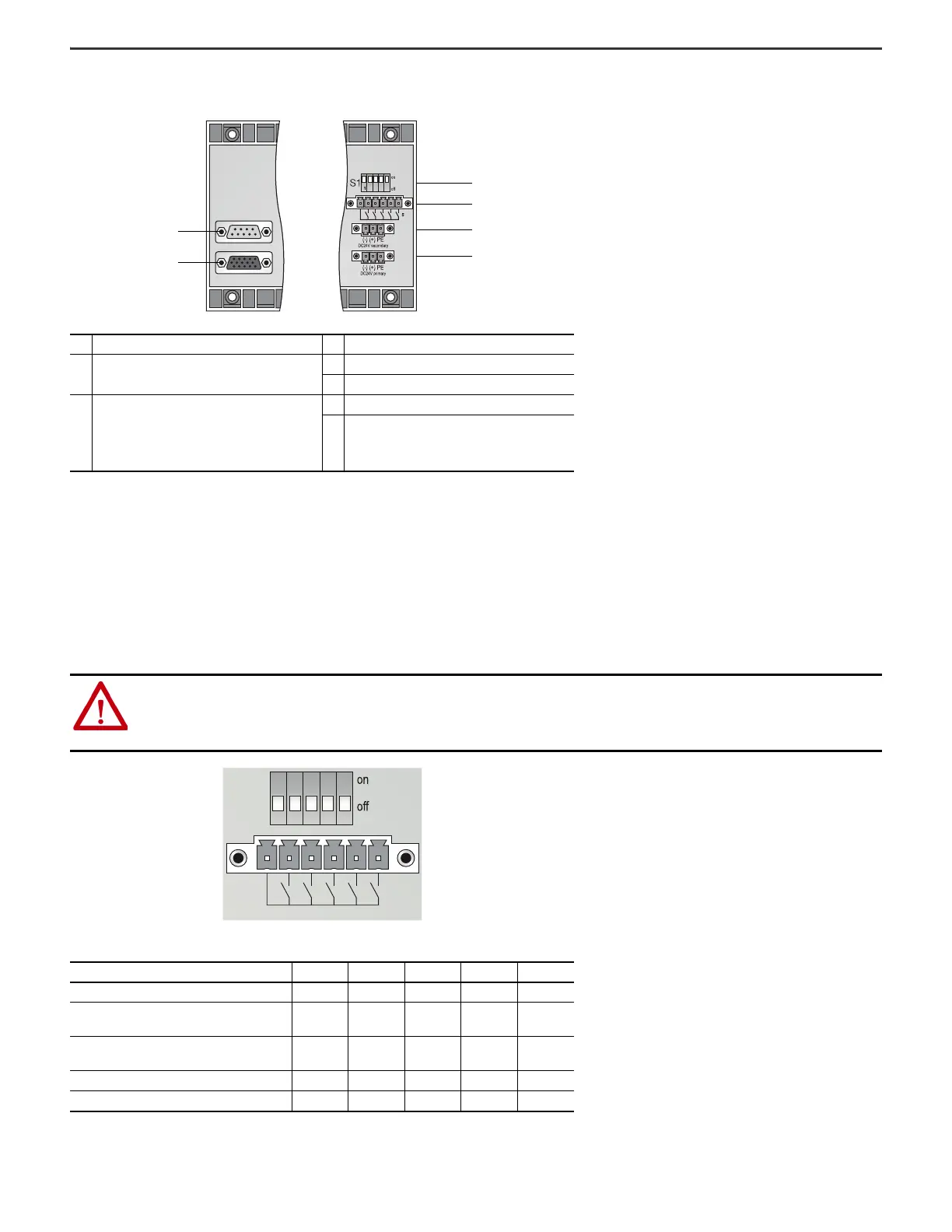
1719-A22, 1719-A24 Connections
S1 Switch Positions and X03 Terminal Assignment (1719-A22, 1719-A24)
The S1 switch and X03 terminal control the output deactivation of the I/O modules.
The output deactivation of the I/O modules only works for I/O modules that are equipped with a deactivation feature (1719-OB2, 1719-OB2L). I/O modules with and without a
deactivation feature can be installed on the same backplane; however, only the I/O modules that are equipped with a deactivation feature are controlled by the output
deactivation.
The backplanes are divided into five areas. Each area monitors different slots on the backplane. If I/O modules that are equipped with a deactivation feature are installed
on the backplane, the individual areas can be deactivated using an external switch.
Description Description
1
X6: Service interface. Currently not used.
Not present in 1719-A24 extension chassis.
3S1: Function switch
4 X03: Output deactivation of the I/O modules
2
X7: Extension connection for 1719-A24
extension chassis.
Note: Online addition of an extension
backplane while the system is in Run mode is
not supported.
5 X02: 24V DC redundant power supply
6 X01: 24V DC power supply
ATTENTION: Damage to equipment
• Do not handle connections improperly as this can damage the backplane.
• Never supply a control voltage to X03.2…X03.6. On backplanes 1719-A22 and 1719-A24, output deactivation of the I/O modules can be controlled by a
voltage-free contact only.
• Only operate multiple adjacent backplanes using a common contact to avoid equalizing currents.
Backplane Areas
Area 1 2 3 4 5
1719-A22 slots 1…3 4…8 9…13 14…18 19…22
1719-A24 slots
(when used with 1719-A22 base backplane)
23…27 28…32 33…37 38…42 43…46
1719-A24 slots
(when used with 1719-A8 base backplane)
9…13 14…18 19…23 24…28 29…32
S1 switch S1.1 S1.2 S1.3 S1.4 S1.5
X03 contact X03.2 X03.3 X03.4 X03.5 X03.6
1
2
3
4
5
6
Left side Right side
X03
S1
 Loading...


