EasyManuals Logo

Rockwell Automation Allen-Bradley MicroLogix 1400 User Manual

Rockwell Automation Allen-Bradley MicroLogix 1400
310 pages
To Next Page IconTo Next Page
To Previous Page IconTo Previous Page
Page #214 background imageLoading...
Page #214 background image
214 Rockwell Automation Publication 1766-UM001O-EN-P - September 2021
Appendix F MicroLogix 1400 Distributed Network Protocol
Overview
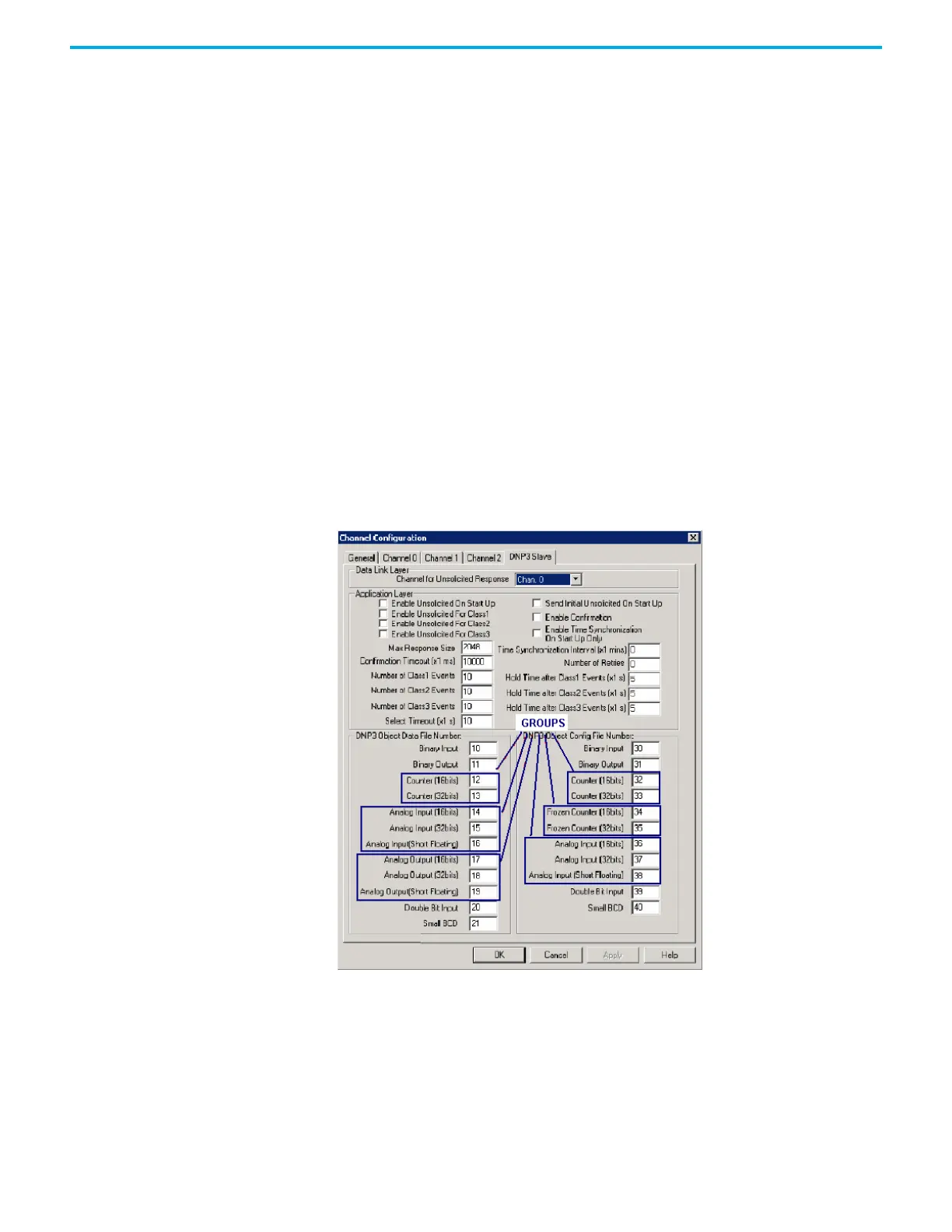
DNP3 Data objects that are implemented in the controller are listed below:
•DNP3 Binary Input Object
DNP3 Double Bit Binary Input Object
•DNP3 Binary Output Object
DNP3 Counter Object
•DNP3 Frozen Counter Object
•DNP3 Analog Input Object
•DNP3 Analog Output Object
•DNP3 BCD Object
DNP3 Data-Set Object (Series B and Series C controllers only)
Some of objects are divided into several Object files to map data files in the
controller.
Counter Object — 16-bit and 32bit Counter Object File
Analog Input Object — 16-bit and 32bit Analog Input Object File, and
Short Floating Point Analog Input Object File.
Analog Output Object — 16-bit and 32bit Analog Output Object File, and
Short Floating Point Analog Output Object File.
For MicroLogix 1400 Series A controllers:

Table of Contents

Questions and Answers:

Question and Answer IconNeed help?

Do you have a question about the Rockwell Automation Allen-Bradley MicroLogix 1400 and is the answer not in the manual?

Rockwell Automation Allen-Bradley MicroLogix 1400 Specifications

General IconGeneral
ModelMicroLogix 1400
Controller TypeProgrammable Logic Controller (PLC)
Processor Type32-bit RISC
Programming SoftwareRSLogix 500
Programming LanguageLadder Logic
Input Voltage24V DC
Analog Outputs2
Communication Ports1 x Serial (RS-232/RS-485)
Expansion CapabilityYes, via expansion I/O modules
Operating Temperature0 to 60 °C
High-Speed CounterYes

Related product manuals