Rockwell Automation Publication 1766-UM001O-EN-P - September 2021 43
Chapter 3 Wire Your Controller
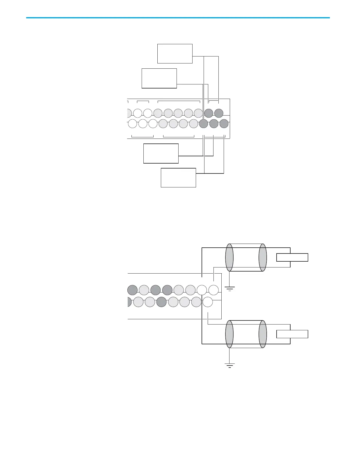
Wire Your Analog Channels Analog input circuits can monitor voltage signals and convert them to serial
digital data.
The controller does not provide loop power for analog inputs. Use a power
supply that matches the transmitter specifications as shown.
The analog output can support a voltage function as shown in the following
illustration.
Figure 20 - Analog Output
Analog Channel Wiring Guidelines
Consider the following when wiring your analog channels:
• The analog common (COM) is connected to earth ground inside the
module. These terminals are not electrically isolated from the system.
They are connected to chassis ground.
• Analog channels are not isolated from each other.
IV0(+) IV2(+)
IV1(+) IV3(+)
/7
COM 2
I/8 I/10
I/9 I/11
COM 3
I/13 I/15 I/17 I/19
I/12 I/14 I/16 I/18
COM
ANA
Input Terminal Block
Sensor 2 (V)
voltage
Sensor 3 (V)
voltage
Sensor 0 (V)
voltage
Sensor 1 (V)
voltage
OV1O/3 O/4
O/5
O/7 O/8 O/10
O/6 O/9 O/11
OV0
3
C
DC4
VAC
DC6
VAC
COM
ANA
DC5
VAC
Output Terminal Block

 Loading...


