1-14 Installation/Wiring
I/O Wiring Examples
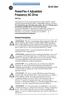
Input Connection Example
Potentiometer
1-10k Ohm Pot.
Recommended
(2 Watt minimum)
P038 [Speed Reference] = 2 “0-10V Input”
Analog Input
0 to +10V, 100k ohm
impedance
4-20 mA, 100 ohm
impedance
Voltage
P038 [Speed Reference] = 2 “0-10V
Input”
Current
P038 [Speed Reference] = 2
“4-20mA Input”
2 Wire SRC Control -
Non-Reversing
P036 [Start Source] = 2, 3
or 4
Input must be active for
the drive to run. When
input is opened, the drive
will stop as specified by
P037 [Stop Mode].
If desired, a User Supplied
24V DC power source can
be used. Refer to the
“External Supply (SRC)”
example.
Internal Supply (SRC) External Supply (SRC)
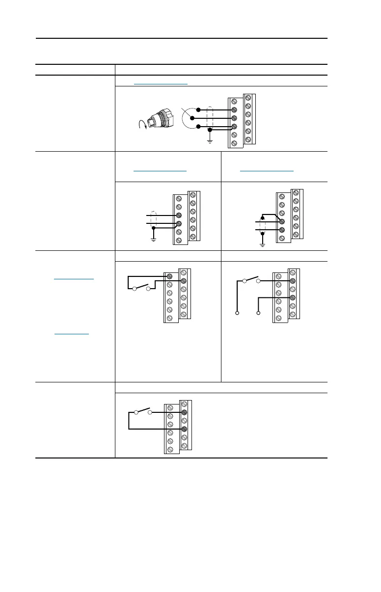
2 Wire SNK Control -
Non-Reversing
Internal Supply (SNK)
12
13
14
13
14
+
Common
14
15
Common
+
11
02
Stop-Run
+24V Common
02
04
Stop-Run
02
04
Stop-Run
Each digital input draws 6 mA.
userman.book Page 14 Friday, June 21, 2002 2:48 PM
 Loading...