102 Rockwell Automation Publication 750-RM100A-EN-P - August 2019
Chapter 11 Application References
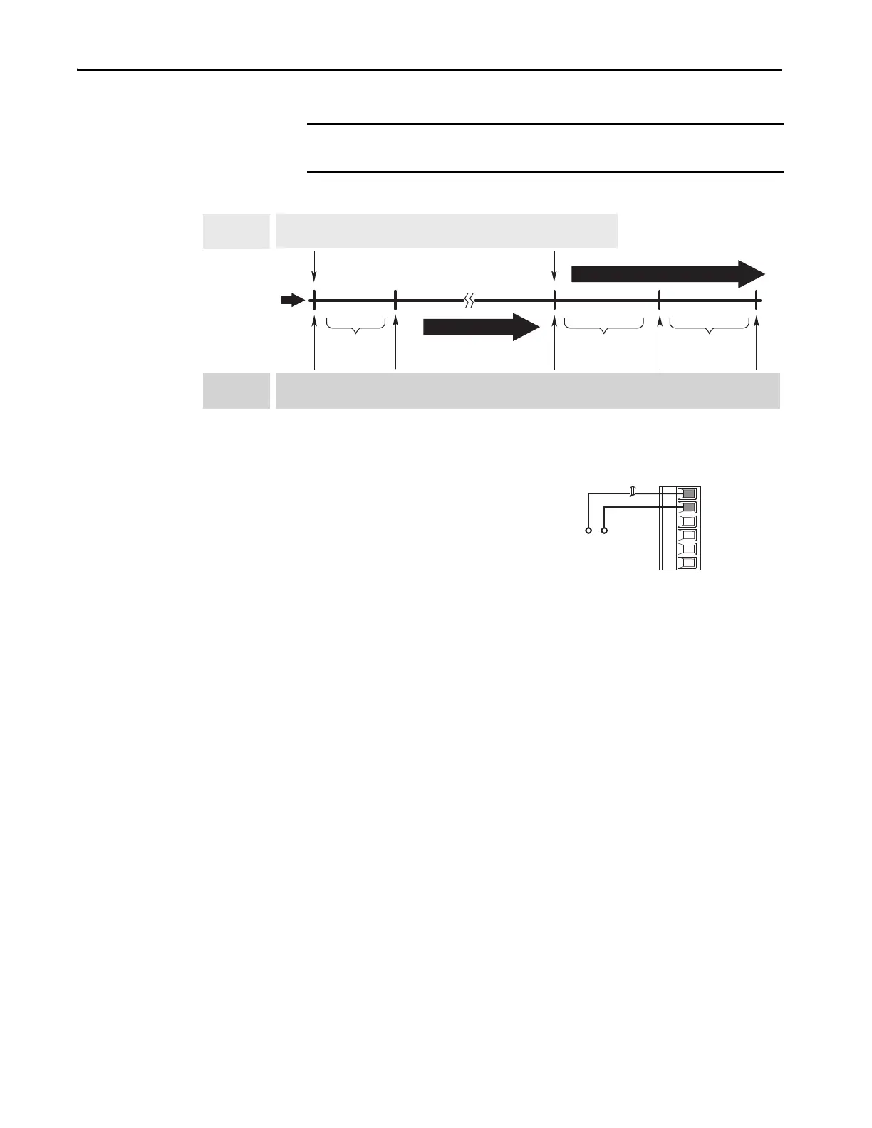
Figure 44 - Torque Proving Flow Diagram
(1) For torque proving to function properly, wire a mechanical brake to a
relay output on a digital I/O option module. On the I/O module, set
nn:10 [RO0 Sel] to 9:52 [Trq Prove Status] Bit 4 ‘Brake Set’ and set nn:6
[Dig Out Invert] Bit 0 ‘Relay Out 0’ = 1.
Brake Slip Test
If an encoder is being used, by default, the drive does a brake slip test on every
stop. The brake slip test is outlined in the following steps.
1. A stop command is initiated
2. The drive ramps to zero speed. A snap shot (one time recording) of the
command torque 10/11:2087 [Trq Ref Limited] is taken.
3. The drive runs at zero speed for the time that is defined in 9:72
[ZeroSpdFloatTime].
4. The drive engages the brake.
5. The drive continues to command the snap shot torque that is found in
Step 2 for the time that is allotted in 9:61 [Brk Set Time].
6. The PowerFlex 755T drive begins to slew (lower) the torque down.
Parameters 10/11:2083 [Torque Limit Pos] and 9:53 [Trq Limit Slew
Rate] define the rate at which the torque is lowered. The starting point of
the ramp is the commanded torque that is found in Step 2 plus 20%
torque. The drive continues to command the torque that is defined in Step
2 until the ramp goes below this torque.
IMPORTANT Brake Slip detection and Float capability (ability to hold load at zero speed) are
no available in encoderless TorqProve.
Torque
Prove Initiated
Brake
Released
Float
Initiated
Brake
(1)
Set
Brake
Slip Test
Run
Run
Command Released
Drive Running
Run can be initiated any time
All times between Drive Actions are programmable and can be made very small
(for example, Brake Release Time can be 0.1 seconds)
9: 72 [ZeroSpdFloatTime]
9:60 [Brk Release Time]
9:61 [Brk Set Time]
Operator
Control
Voltage
R0NO
I/O Module TB2
Brake
 Loading...


