12 Rockwell Automation Publication 750-RM100A-EN-P - August 2019
Chapter 1 Adaptive Control
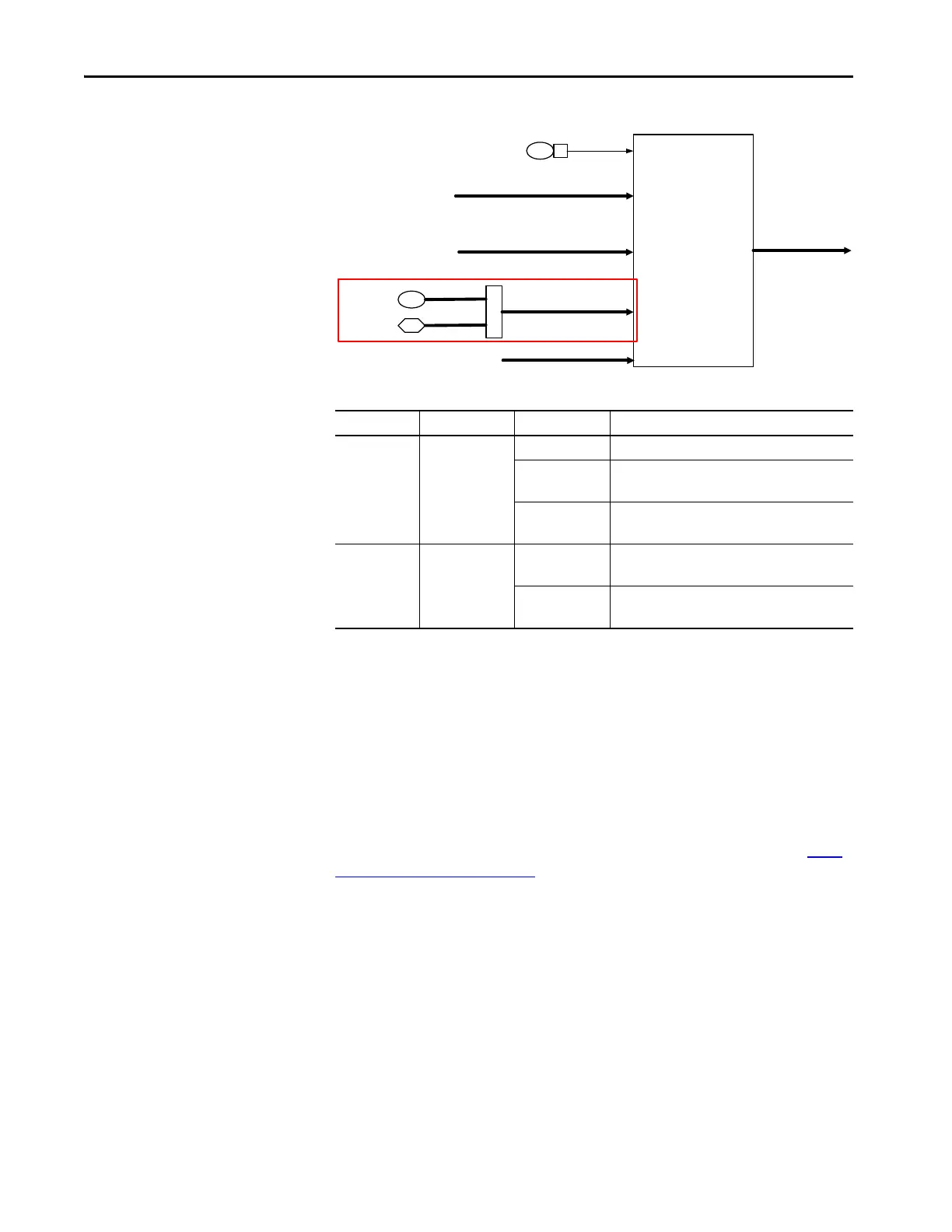
Figure 4 - Feed Forward Power Block Diagram
Reference Notch Filters
PowerFlex 755T products include two reference notch filters. There are three
instances in which these two filters share a set of common parameters. The
instances are located in the Velocity, Position, and Process PI command paths.
These reference notch filters help prevent the velocity command from
introducing a resonance into the mechanical system or sway into a crane/hoist
system.
You can use the reference notch to counter the pendulum effect that is caused by
the movement of the trolley or gantry in crane and hoist applications. See Anti-
Sway Applications on page 121 information about configuring notch filters for
crane/hoist applications.
Technical Overview
The two notch filters in the velocity reference and position reference paths can be
used to notch out command frequencies that can cause resonance or instability in
mechanical systems. The notch filters have the following restrictions:
• Available in Flux Vector control modes only.
• Cannot be used in Sensorless Vector or Volts/Hz modes.
Table 1 - Feed Forward Power Parameters
Parameter No. Parameter Name Setting Description
13:300 BusDistRej Mode 0 = ‘Disabled’ The control uses no special method.
1 = ‘Bus Observer’ The control applies Bus Observer.
This setting is recommended for 755TM bus supplies.
2 = ‘FF Power’ The control applies the feed forward power method.
This setting is recommended for 755TL/TR drives.
13:320 BusObs Mode 0 = ‘BusObs Only’ Bus Observer Only mode.
Use this setting when the bus capacitance is known.
1 = ‘BusObsVltEst’ Bus Observer with voltage estimate mode.
Use this setting when the bus capacitance is unknown.
Converter Mode Select
40 2
Conv Options Cfg
CurRefGen [F2]
VoltCtrl [H2]
PFC [A2,E2,A4,E4]
10:4
13:44
FF Power Gain
Output Power
X
DC Bus Obs[H2]
IqRefDcBusObs
 Loading...


