18 Rockwell Automation Publication 750-RM100A-EN-P - August 2019
Chapter 2 AC Line Tuning
AC Source Configuration
The first step to configure the converter is to specify some basic information
about the AC source. This basic information is used to calculate the system
impedance, which is used to calculate the current regulator gains automatically.
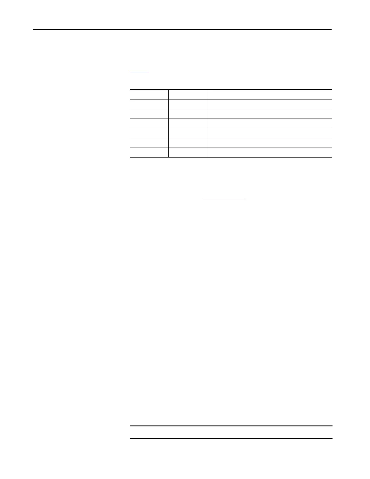
Tab le 3
shows the basic AC line source information required.
System impedance is derived from this information. The converter operates best
when system impedance is less than 10%. Use this equation to calculate system
impedance.
The Line Source A and Line Source B parameters accommodate situations where
the system is powered by two separate sources. An example is when the system has
a backup generator that switches on when the main AC line loses power.
If the drive is not going to be powered by different sources, populate only one set
of line source data (A or B). Which set is populated does not matter as long as
13:31 [AC Line Source] is pointing to the set with the correct line information.
External Bus Capacitance
When tuning the converter, some analogies can be made to tuning the inverter.
One analogy is the similarity between external bus capacitance and load inertia.
Just like inertia resists changes in velocity on the motor side, bus capacitance
resists changes in DC Bus Voltage on the line side. Having the correct external
bus capacitance is as important to the Voltage Regulator gains as having the
correct load inertia is to the Velocity Regulator gains.
The total system capacitance is used in the automatic calculation of the voltage
regulator gains. Total system capacitance is the sum of all capacitance that is
connected to the DC bus. The drive knows its own capacitance and
automatically accounts for it in the calculations, but it does not know the
capacitance of external devices that are connected to the bus. Use parameter
13:52 [Ext Bus Cap] to specify the external capacitance so that the total system
capacitance is known. External bus capacitance is the sum of the individual bus
capacitance values for each drive and any external bus capacitors that are
connected to the DC bus.
Table 3 - AC Line Source Data
Parameter No. Parameter Name Definition
13:30 Nom Line Freq 0 = 50 Hz, 1 = 60 Hz
13:31 AC Line Source 0 = AC Line A, 1 = AC Line B
13:32 AC Line kVA A Apparent Power Rating for AC Line Source A
13:33 AC Line kVA B Apparent Power Rating for AC Line Source B
13:34 AC Line Imped% A Impedance of AC Line Source A in %
13:35 AC Line Imped% B Impedance of AC Line Source B in %
System Impedance =
PowerFlex 755T KV A
Transformer KV A
IMPORTANT Do not overstate the external bus capacitance.
 Loading...


