Rockwell Automation Publication 750-RM100A-EN-P - August 2019 23
AC Line Tuning Chapter 2
Proper adjustment of the individual proportional and integral terms is more
difficult than adjusting the bandwidth because the ideal spacing between the
proportional and integral terms is not maintained. The theoretical ideal spacing
between the proportional and integral terms is where Z = 1 is the desired
damping factor. This creates a 4:1 spacing.
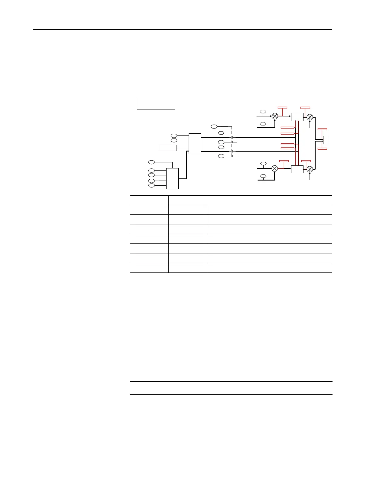
Figure 11 - Current Control (CurrCtrl) Regulator and Gains Block Diagram
AC Line Source Switching
PowerFlex 755T regenerative AFE products can switch between two different
AC line sources. Set parameter 13:31 [AC Line Source] to point to the active AC
line (AC Line A or AC Line B). With firmware revision 3 and earlier, set
parameter 13:31 [AC Line Source] using the HIM, Connected Components
Workb ench sof t ware , o r d ata li n k s .
With firmware revision 4 and later, you can use a digital input to switch between
AC line sources. Set parameter 0:136 [DI AC LineSource] to the digital input
that you want to use to switch sources. When the digital input is off, the
converter uses AC Line A and when it is on, it uses AC Line B.
When switching between two AC line sources, it is important that the converter
is tuned to both sources. Individual AC line sources rarely have the same
electrical characteristics. Gains that work well for one source can cause resonance
when connected to the alternate source.
Parameter No. Parameter Name Definition
13:74 Cur Reg C/U Sel 0 = Calculated, 1 = User Entered, 2 = Load Calculated Data
13:75 Cur Reg BW Current regulator bandwidth in Hz
13:76 Cur Reg Damping Current regulator damping factor
13:77 u Cur Reg Kp User entered current regulator proportional gain
13:78 c Cur Reg Kp Calculated current regulator proportional gain
13:79 u Cur Reg Ki User entered current regulator integral gain
13:80 c Cur Reg Ki Calculated current regulator integral gain
Auto Gain
Calculation
PI Regulator
75
76
Cur Reg BW
Cur Reg Damping
0
1
74Cur Reg C/U Sel
LCL Data
0
1
79
u Cur Reg Ki
77
u Cur Reg Kp
Source
Impedance
Processing
32
34
AC Line kVA A
Line Imped% A
31AC Line Source
33
35
AC Line kVA B
Line Imped% B
c Cur Reg Ki
80
c Cur Reg Kp
78
Active Current
7
Active Cur Cmd
67
PI Regulator
Reactive Current
8
Reactv Cur Cmd
73
CurPwrLmt [G3]
CurPwrLmt [G4]
Metering [I1]
Metering [I2]
P
W
M
IqSyncErr
IdSyncErr
VqSyncRef
VdSyncRef
CurRegKiIq
CurRegKpId
CurRegKpIq
CurRegKiId
PFC [G3]
PFC [G4]
CurRegqOut
CurRegdOut
Cur Reg C/U Sel Selector:
0- Calculated
1- User Entered
IMPORTANT Do not switch AC line sources while the converter is modulating.
 Loading...


