Rockwell Automation Publication 750-RM100A-EN-P - August 2019 13
Adaptive Control Chapter 1
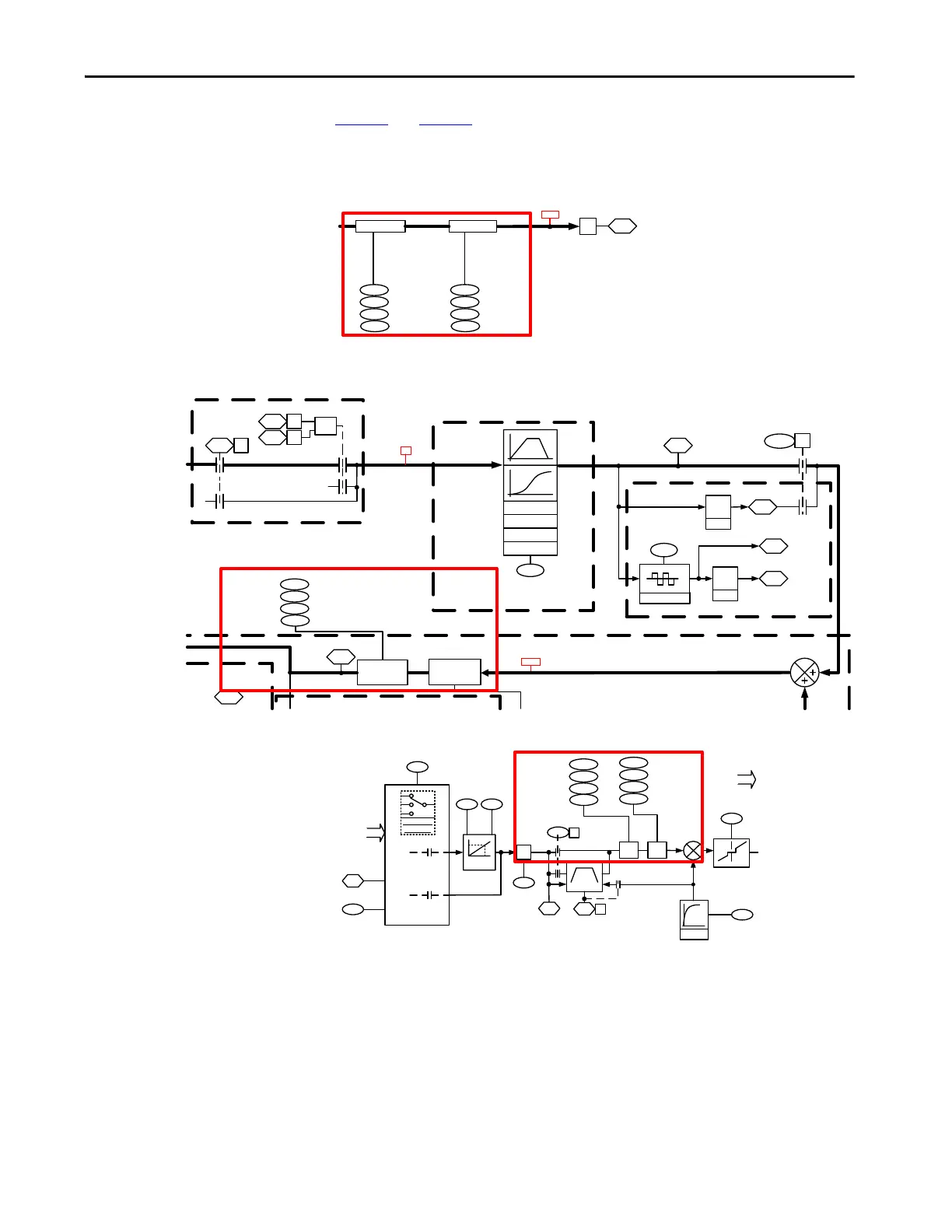
Figure 5 and Figure 6 show that the notch filters are located in the reference
command of both the position and velocity command paths.
Figure 5 - Position Reference 2 (PRef2) Block Diagram
Figure 6 - Velocity Reference – Flux Vector (VRef Vect)
Figure 7 - Process PID (Proc1) Block Diagram Block Diagram
d
15
Ref NF 2Ref NF 1
PRef NF Out
PReg [C3]
948
950
949
951
Ref NF2 Freq
Ref NF2 Depth
Ref NF2 Width
Ref NF2 Gain
942
944
943
945
Ref NF1 Freq
PRef EGR Out
Ref NF1 Depth
Ref NF1 Width
Ref NF1 Gain
PRef NF Out
¦
2070
Accel FF Output
1924
Virtual Encoder
1017
1046
VRef Delayed
Virtual Enc Psn
Virtual EncDelay
One
Scan
Delay
One
Scan
Delay
1923
VRef Ramped
Velocity Comp
Virtual Encoder
Velocity Ramp and Move Profiles (VRef Move)
1018
Virtual Enc EPR
(Edges Per Rev)
1
0
Vel Ctrl Options
(Delayed Ref)
Proc 2 [C2]
PRef 1 [C5]
0
354
18
1
0
Motor Side Sts 1
(Stopping)
1
0
0
Stopping
or Not Active
Not Stopping
and Active
OR
Motor Side Sts 1
(Running)
Motor Side Sts 2
(Autotuning)
354
16
355
9
1950
8
Ref NF2
1925
Ref NF1
36
PRef 1 [C5]
948
950
949
951
Ref NF2 Freq
Ref NF2 Depth
Ref NF2 Width
Ref NF2 Gain
1
VRef Ramp In
VRef NF In
Ref Move Type
931
LinScurve
SineSquared
Poly5
Cubic
Vel Comp Sel
VRef Filter
P
ID Setpoint
Default
9:28
9:29
9:30
Scale
PID Ref
AnlgHi
PID Ref
AnlgLo
1823
PID Ref Sel
9:25
Analog Types
Float Types
x
9:27
PID Ref
Mult
9:26
PID Ref
Meter
Ramp
9:1
1
1
0
Error Deadband
9:9
PID
Deadband
PID Cfg
(Ramp Ref)
PID Status
(PID Enabled)
9:3
0
9:10
PID LPF
BW
0
Parameter
Selection
Option
Port:
Analog In
Option
Port:
Digital In
Ref
NF1
LPass
Filter
Ref
NF2
945
951
942
944
943
Ref NF1 Freq
Ref NF1 Depth
Ref NF1 Width
Ref NF1 Gain
948
950
949
Ref NF2 Freq
Ref NF2 Depth
Ref NF2 Width
Ref NF2 Gain
M
 Loading...


