14 Rockwell Automation Publication 750-RM100A-EN-P - August 2019
Chapter 1 Adaptive Control
Notch Filters Examples
These graphs show a velocity command before and after the reference notch
filter. The command going into the filter is a ramp to 50 rpm in 0.5 seconds and
the first notch filter is set to a frequency of 0.5 Hz.
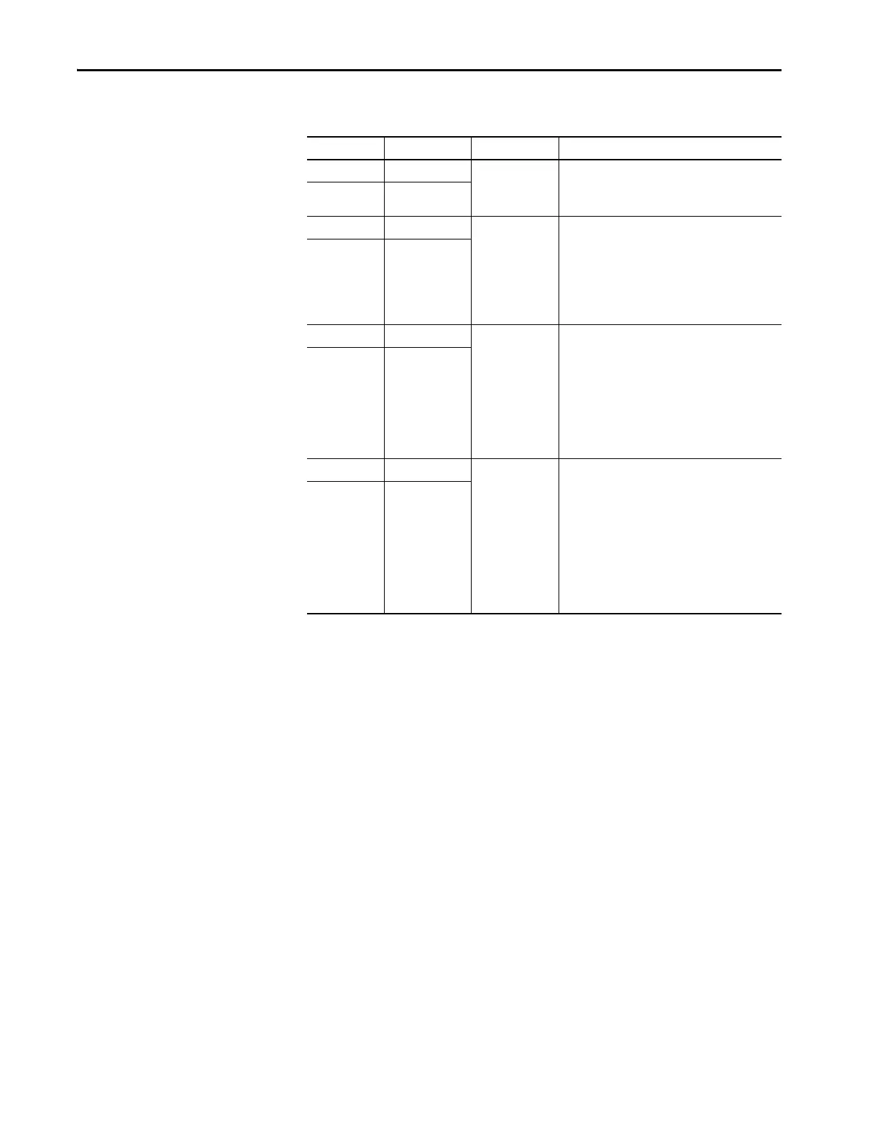
Table 2 - Notch Filter Parameters
Parameter No. Parameter Name Setting Min/Max Description
10/11:942 Ref NF1 Freq 0.00/32767.00 Hz
Reference Notch Filter Frequency
Enter the center frequency of the first reference notch
filter in units of Hz.
10/11:948 Ref NF2 Freq
10/11:943 Ref NF1 Width 0.000/10000.000 Reference Notch Filter Width
Enter the width of the first reference notch filter
around the center frequency.
This value determines the denominator damping of its
second order transfer function.
A typical value of 0.4 produces a narrow width and a
value of 1.0 produces a wide width.
10/11:949 Ref NF2 Width
10/11:944 Ref NF1 Depth 0.000/10000.000 Reference Notch Filter Depth
Enter the depth of the first reference notch filter at the
center frequency.
This value determines attenuation level and the
numerator damping of its second order transfer
function.
The minimum depth occurs when this value is the
same value as the width, turning off the filter. The
maximum depth occurs when this value is zero.
10/11:950 Ref NF2 Depth
10/11:945 Ref NF1 Gain -20.00/+20.00 Command (Reference) Notch Filter Gain
Enter the gain of the first reference notch filter.
This value sets the mode of the filter and gain of its
second order transfer function.
For a notch filter, enter a value of 1.
For a second order low pass filter, enter a value of 0.
For a second order lag-lead filter, enter a value from 0
to 1.
For a second order lead-lag filter, enter a value greater
than 1.
10/11:951 Ref NF2 Gain
 Loading...


