PowerFlex 700S Phase II Drives DriveLogix Option Card Battery Extension Cable 3
Step 2: Accessing the
700S Phase II Control
Refer to the proper instructions for your drive frame size:
• See “Frames 1 - 6 Size Drives” below
• See “Frame 9 Size Drives” on page 4
• See “Frame 10 - 13 Size Drives” on page 4
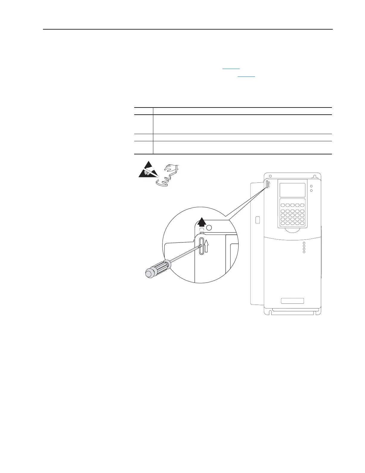
Frames 1 - 6 Size Drives
Frame Action
1 - 4 Locate the slot in the upper left corner (as shown below). Slide the locking tab up and swing
the cover open. Special hinges allow the cover to move away from drive and lay on top of an
adjacent drive (if present).
5 Slide the locking tab up, loosen the right-hand cover screw and remove the cover.
6 Loosen the two screws at bottom of the drive cover. Carefully slide the bottom cover down
and out. Loosen the two screws at top of cover and remove the cover.
=
 Loading...


