4 PowerFlex 700S Phase II Drives DriveLogix Option Card Battery Extension Cable
Frame 9 Size Drives
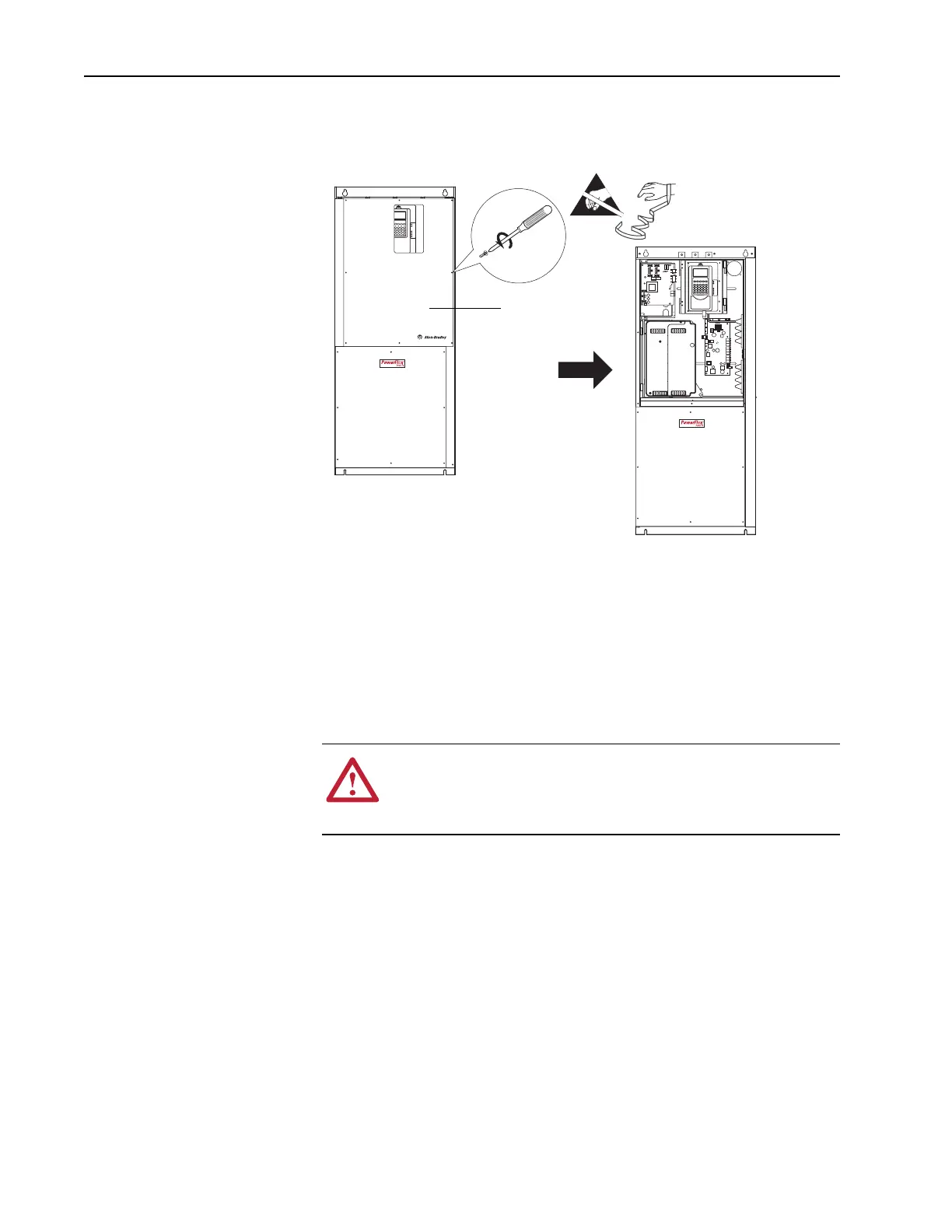
1. Remove the connection cover as indicated below. Save screws for reuse.
Frame 10 - 13 Size Drives
1. Open the enclosure door for the cabinet that holds the control assembly.
Step 3: Removing the
700S Phase II Control
Assembly from the Drive
It is necessary to remove the Phase II control assembly from the drive in
order to install the new DriveLogix option card battery extension cable.
Important: Before removing connections and wires, mark the connections
and wires to avoid incorrect wiring during assembly.
L1 L2 L3 L1 L2 L3 U/T1 V/T2 W/T3 U/T1 V/T2 W/T3
(8 Screws)
Connection Cover
=
!
ATTENTION: Hazard of permanent eye damage exists when
using optical transmission equipment. This product emits intense
light and invisible radiation. Do not look into fiber-optic ports or
fiber-optic cable connectors.
 Loading...


