1-18 Installation/Wiring
PowerFlex 40 Adjustable Frequency AC Drive FRN 1.xx - 7.xx User Manual
Publication 22B-UM001I-EN-E
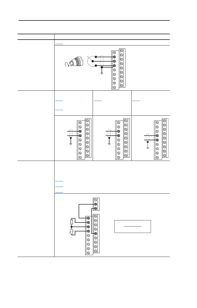
I/O Wiring Examples
Input/Output Connection Example
Potentiometer
1-10k Ohm Pot.
Recommended
(2 Watt minimum)
P038
[Speed Reference] = 2 “0-10V Input”
Analog Input
0 to +10V, 100k ohm
impedance
4-20 mA, 250 ohm
impedance
Bipolar
P038
[Speed Reference]
= 2 “0-10V Input” and
A123
[10V Bipolar Enbl]
= 1 “Bi-Polar In”
Unipolar (Voltage)
P038
[Speed Reference]
= 2 “0-10V Input”
Unipolar (Current)
P038 [Speed Reference]
= 3 “4-20mA Input”
Analog Input, PTC
For Drive Fault
Wire the PTC and External Resistor (typically matched to the PTC Hot
Resistance) to I/O Terminals 12, 13, 14.
Wire R2/R3 Relay Output (SRC) to I/O Terminals 5 & 11.
A051
[Digital In1 Sel] = 3 “Aux Fault”
A055
[Relay Out Sel] = 10 “Above Anlg V”
A056
[Relay Out Level] = % Voltage Trip
12
13
14
13
14
-/+ 10V
Common
14
15
Common
+
11
12
13
14
R2
R3
05
V
Tr i p
=
×
100
R
PTC (hot)
R
PTC (hot)
+ R
e
R
e
R
PTC
22B-UM001.book Page 18 Tuesday, May 30, 2017 5:22 PM

 Loading...


