Micro810 12 Point Programmable Controllers 9
Publication 2080-IN006A-EN-P - September 2010
To remove your controller from the DIN rail, pry the DIN rail latch downwards until it is in
the unlatched position.
Panel Mounting
The preferred mounting method is to use four M4 (#8) screws per module. Hole spacing
tolerance: ±0.4 mm (0.016 in.).
Follow these steps to install your controller using mounting screws.
1. Place the controller against the panel where you are mounting it. Make sure the
controller is spaced properly.
2. Mark drilling holes through the mounting screw holes and mounting feet then remove
the controller.
3. Drill the holes at the markings, then replace the controller and mount it.
Leave the protective debris strip in place until you are finished wiring the controller
and any other devices.
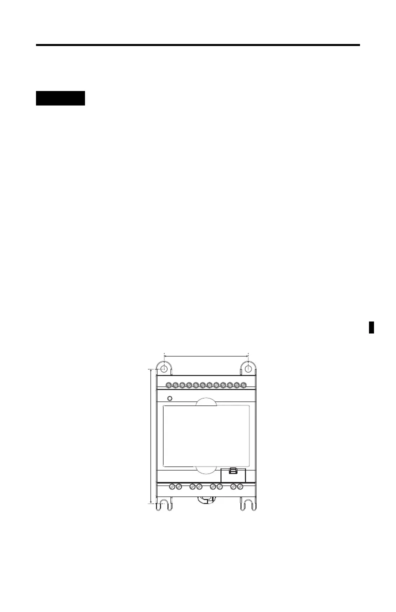
Panel Mounting Dimensions
For environments with greater vibration and shock concerns, use the panel
mounting method, instead of DIN rail mounting.
45324
63 mm (2.48 in.)
100 mm (3.94 in.)

 Loading...


